Little Less Conversation A Little More........
#106

Posted 16 February 2011 - 12:21 PM
#107

Posted 16 February 2011 - 02:18 PM
If you work it out, the two verticals are at 800mm centres, so 800*tan0.2 = 2.8mm
So in fact I managed to notch each side to within 2.8mm, which is OK but actually could be better...
Happy for a first go though...
#108

Posted 16 February 2011 - 02:35 PM
#109

Posted 16 February 2011 - 10:09 PM
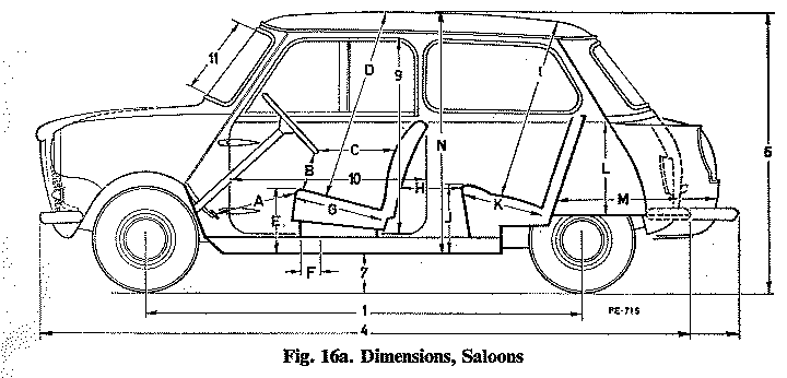
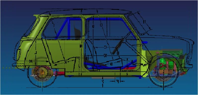
onto one of my screen dumps today. I've not been confident about my front pane position, as I've never seemed to have as much room for the engine in the CAD as I seemed to have when I did the original mock up (right back at the start of this thread).
As it turns out - I need to go up and forwards with my front panel - which gives me quite a bit more room for the engine... which to be fair - I could really use! Also of note - looks like I have the window and door apertures slightly rearwards of true position in my shell model. Always good to know... Not sure if I will bother to change them now, might be an unnecessary ballache... Still... its good to know these things..
#110

Posted 16 February 2011 - 10:13 PM
YetI
#111

Posted 16 February 2011 - 10:31 PM
Yes - that is a Mk1 line drawing... Reassuring. My shell is a MkIII...
Don't suppose anyone knows of a MKIII side profile line drawing do they??
#113

Posted 21 February 2011 - 10:28 PM
#114

Posted 01 March 2011 - 01:31 PM
Well, got a bit more done this weekend out in the garage. I did take some pictures of the shell, but I'm back in spain now and the hard drive of my mac just pitched, so I can't post them until next weekend when I get home again...
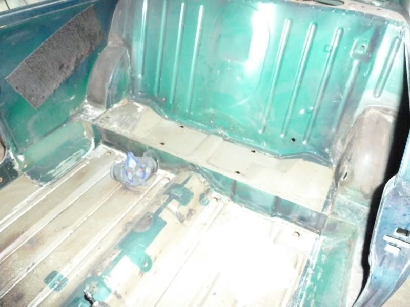
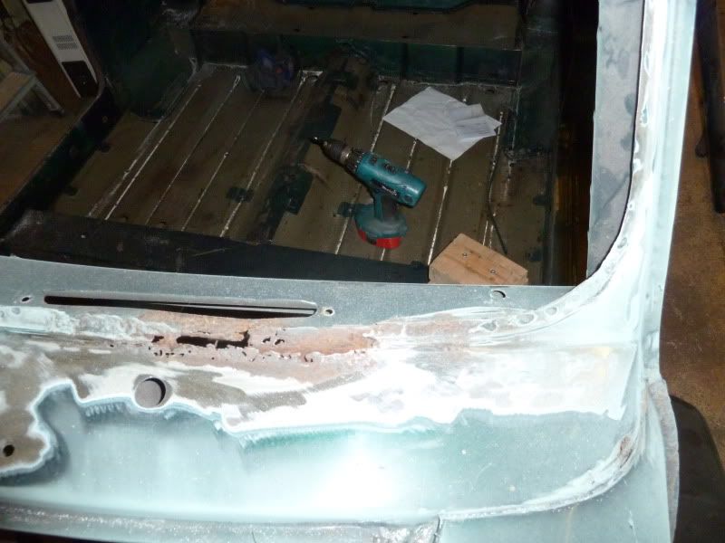
What I did was cut out the door bins and the seat base back to the step at the rear of the floor. I also gave the shell a really good clean and wipe down with thinners to remove all the residual bitumen on the floor panels. Had a run round most of the shell with a flap wheel in the grinder to remove the rusty bits as well. I will need to replace the scuttle (knew this) and do a repair to the driver's side sill where it meets the floor (knew about that too). The rear valance is quite knackered where it meets the boot floor and rear panel (hadn't noticed that before), so that will need to be sorted as well. I do think that mini's look quite cool with that seam removed, so perhaps thats what I'll do there.. not much of a fan of de-seamed cars generally but maybe that one can go.
Still got some seam sealer to get rid of around the back of the floor that was covered by the seat base panel before, and I need to pick up a spot weld drill this week so I can remove the last of the door bins from the floor panel. Floor cross member also needs to go, probably best to drill out the spot welds there too. Something will go in it's place to carry the seats once the transmission tunnel is in place which I still need to design.
On the CAD front, I've changed the main roll structure in the cabin and moved on a bit more with the front subframe.
#115

Posted 01 March 2011 - 01:45 PM
#116

Posted 13 March 2011 - 09:19 PM
Thanks for the comments again...
Here are a couple of CAD images from this weekend and last. It might not look like there is a great deal of progress, but design is a slow process and I feel like I have come a long way in the last couple of weeks...
Last time I showed the front subframe it looked like this:
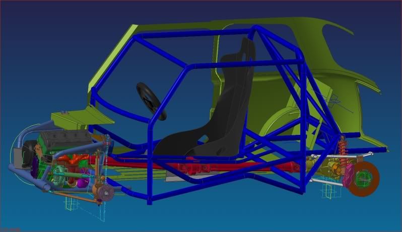
Here's where I am now (still not final - there are a number of strengthening gussets to be added yet)...
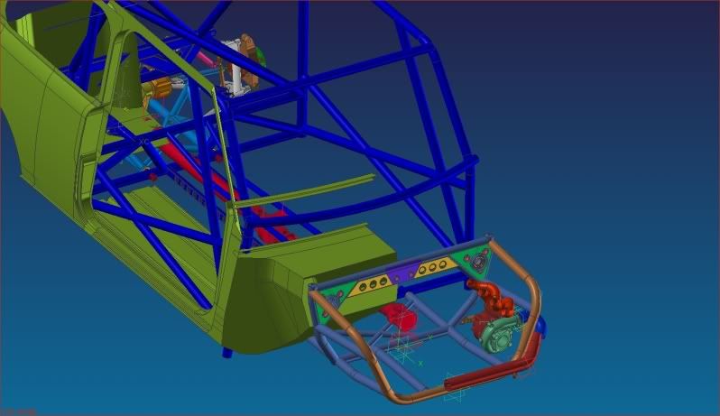
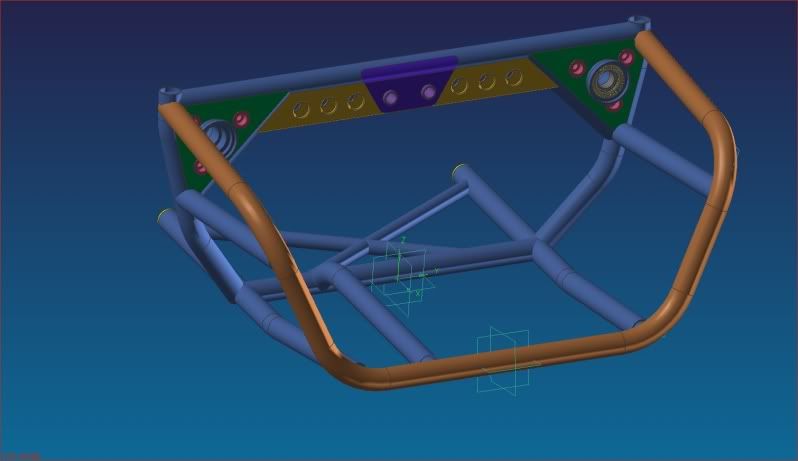
The rear cross bracing at the bottom needs to be the way it is because I can't notch less than 30deg with my equipment....
Otherwise, I have modified the main roll structure as mentioned in the last post...
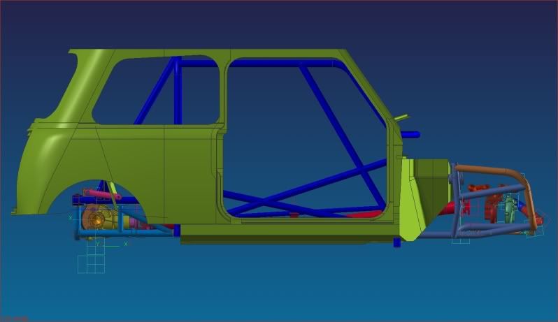
You can see there is still a gap between the front subframe and the blus roll structure in this one - thats really the last big gap now. In order to try and close it I have been looking at the front suspension as a priority now.... The dampers are inside the front bulkhead (for those just tuning in
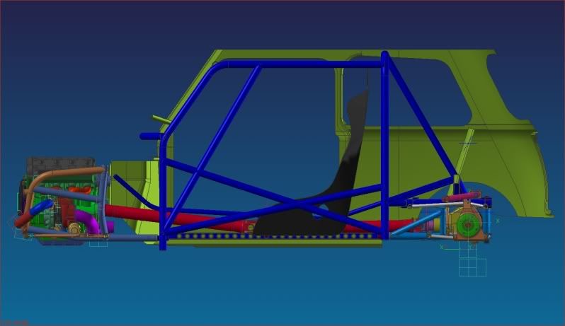
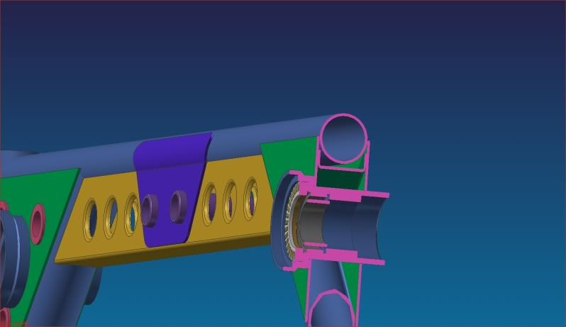
With that in mind, today I have been trying to figure out how the bearing housing for my offset rocker will work. At the moment I'm thinking of using a needle roller bearing with machined inner and outer rings (SKF NA4906 for the geeks - in grey) for the main bearing combined with a needle roller thrust on the front (white with yellow rollers). At the back maybe a combined roller / ball bearing.. not got to grips too much with that yet though.. I want to have a word with one the suspension guys at work to see how its normally done on cars with pushrod suspension... mine will be a bit different being an offset rocker, but I think the bearing arrangements shouldn't be that different in concept - just in terms of the (more) travel and (lower) loads in my case...
In terms of tangible progress on the shell, heres where I have cut out the seat base and the storage bins that I mentioned last time. Much more to come of course but its a start... I've not done anything on it this week, but I did pick up a spot weld drill to take out the panels I need to take out in the most measured way I can (cross members from the floor and bulkhead for example). Until this design work is done there isn't much point getting too ambitious removing bits even though I really want to be at it..!
Scuttle rot - it'll be needing a new one... Anyone used the ones advertised on Ebay? Are they anywhere close to fitting???
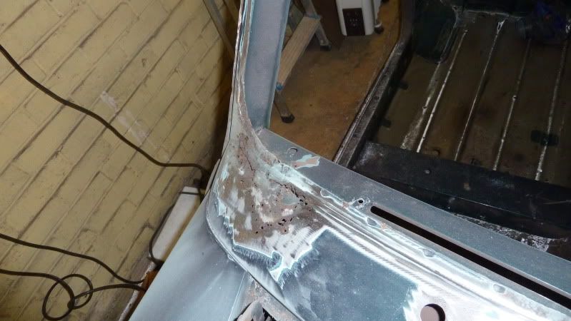
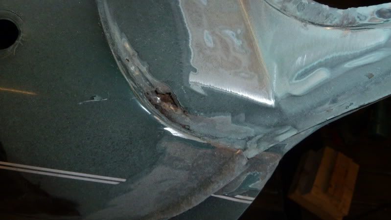
And the repair I need to do to the driver's floor...
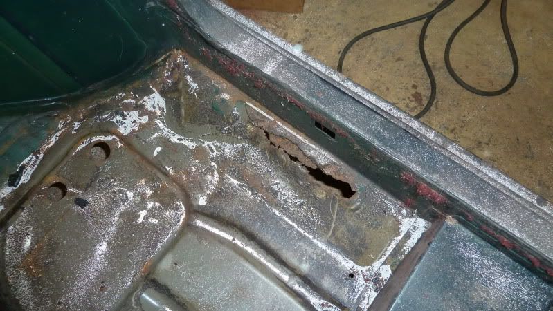
Rear seam that I mentioned..
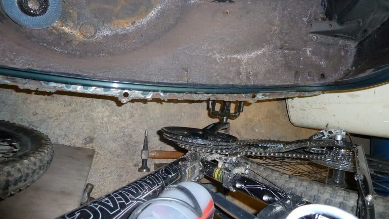
So basically - for a mini shell as these kind of threads go - its absolutely mint! Haha.
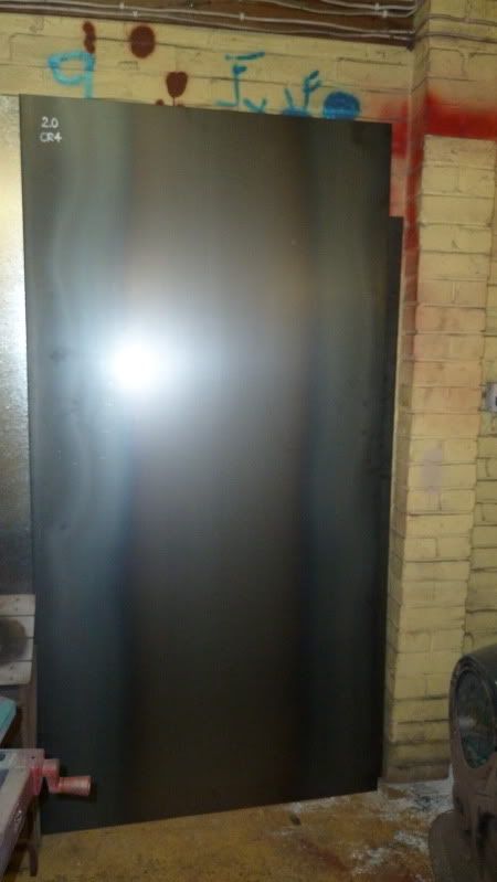
And in other news... I ordered some sheet material. One sheet each of CR4 in 1.0, 1.2, 1.6 and 2.0mm thickness - I have applications for them all in one way or another. You can see the 2.0 here.. Others are beside or behind. Unfortunately the steel stockist only managed to deliver 3 of the sheets, missing out the 1.0mm (for frame gussets mainly I am thinking I'll use 1.0mm), and the 1.2mm they sent is galvanised - so that'll have to go back... grr..
And I also took delivery of some CDS. 25 and 38 OD in 2.5 and 2.0 thickness.... Not enough to do it all, but it will get me started... I also knocked up a rack to store it on the side of my mini-mezzanine (completed the rack last week).... And also found a home for those fairy lights I was gonna chuck out... might as well give the place a bit bling if I'm going to be spending my free time in there more often...
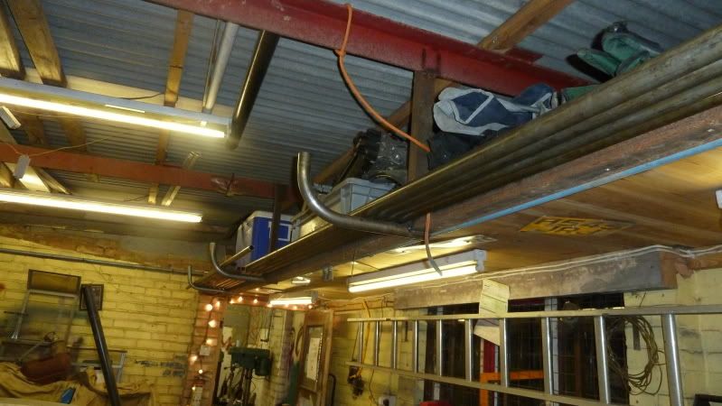
Dave.
#117

Posted 14 March 2011 - 12:56 PM
#118

Posted 14 March 2011 - 04:59 PM
#119

Posted 14 March 2011 - 05:20 PM
#120

Posted 23 March 2011 - 12:56 AM
I've been into the front suspension again this week, and the engine compartment. Hope I can squidge the engine forwards a bit as the exhaust is hitting everything after bringing the subframe tubes closer to where I want the suspension mount points... not added any of the gusset pieces I'm thinking of yet either, so I think the main frame of the front sub still looks a bit light at the moment. Also the charge pipe will need to change again... oh well 2 steps forward, 1 step back..
Wishbones:
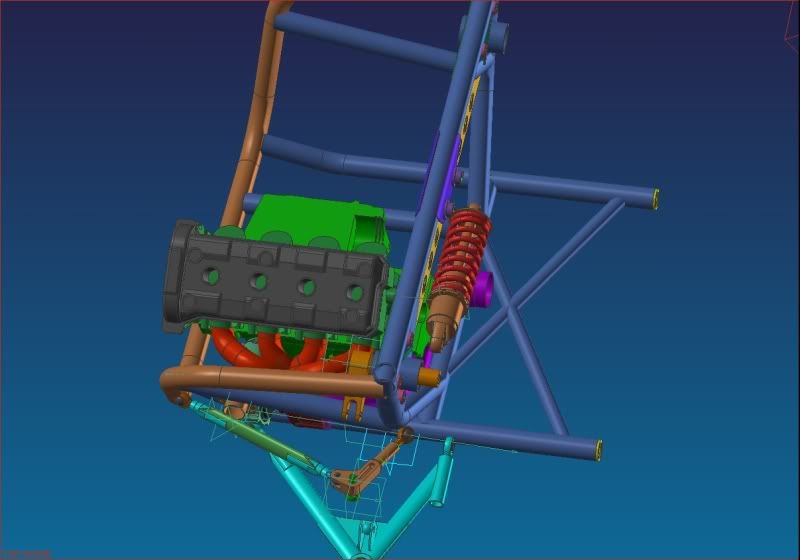
Overtight exhaust (actually clashing with the subframe here)
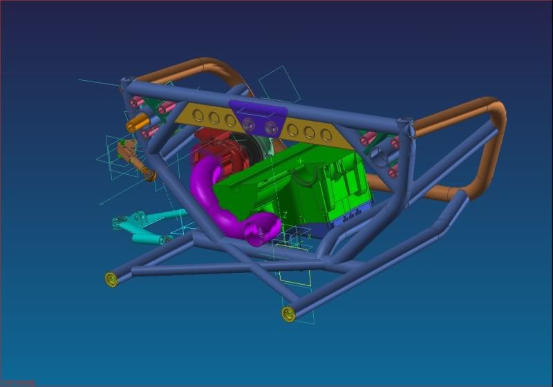
Managed to shrink down the rocker bearing housings though...
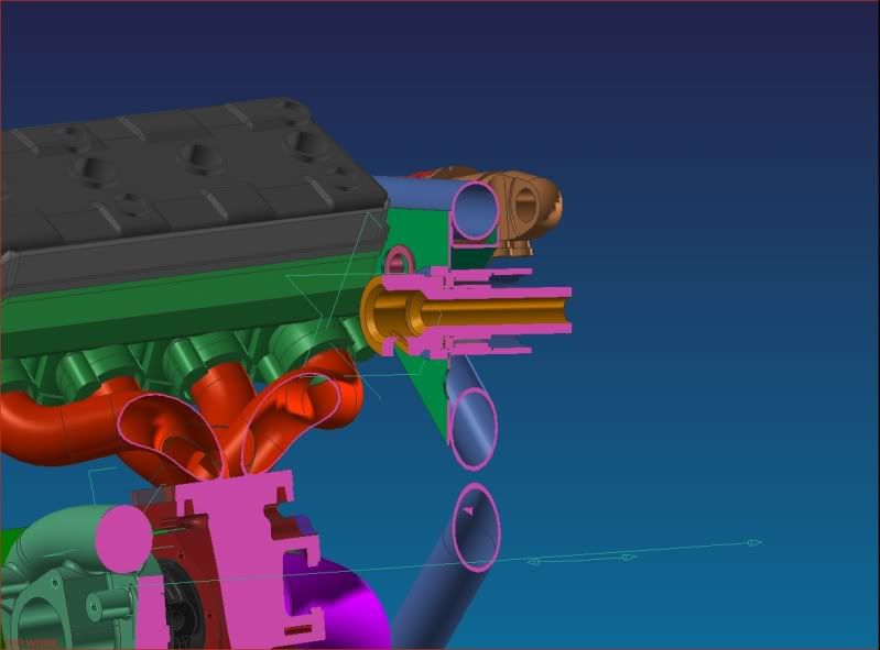
Also an alternator cover turned up today that came from the bay.. I'll model it up and it should help to fix where the back of the engine can go...
Edited by SukiDawg, 23 March 2011 - 01:07 AM.
2 user(s) are reading this topic
0 members, 2 guests, 0 anonymous users


