He was last active in August 2012, seeing this one finished isn't looking so likely.

Little Less Conversation A Little More........
#226

Posted 21 January 2014 - 12:25 PM
#227

Posted 21 January 2014 - 09:26 PM
![]()
#229

Posted 31 May 2015 - 11:51 AM
Read this from the beginning and I must say your cad skills are alot better than mine that's for sure and it's is definately going to be a beast when it's finished
I'll put a pound on it, that it will definately never be finished.
I don't see the point of spending hours and hours coming up with a 3d cad model of a differential for instance, when you can just plonk it in and see if it fits in minutes. He already has the major components, engine, etc to work with
David
Thanks for the feedback David - and I guess with the time I spent I could have put something together and have been running around in it. I just wanted to do it my way and really understand the process... :)
#230

Posted 31 May 2015 - 12:03 PM
In the years in between, I now do most thing in CAD albeit just line drawings, because I'm sick of redoing things when I haven't thought them through properly!
David
#231

Posted 31 May 2015 - 08:46 PM
#232

Posted 31 May 2015 - 10:54 PM
wow that's really a innovative project
You realized that with that short wheelbase of the classic mini RWD is quite tricky on big hp numbers (ok 1 to 60mph its better) if the car should also be fast in curves, pulling instead of pushing is more favorable with this very short wheelbase, 4 wheel drive will be optimum.
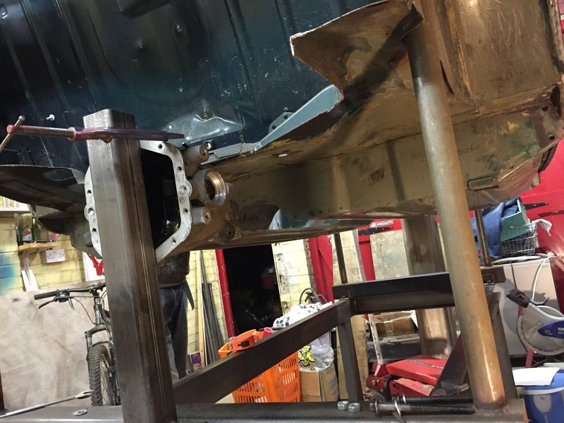
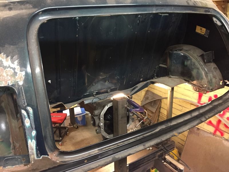
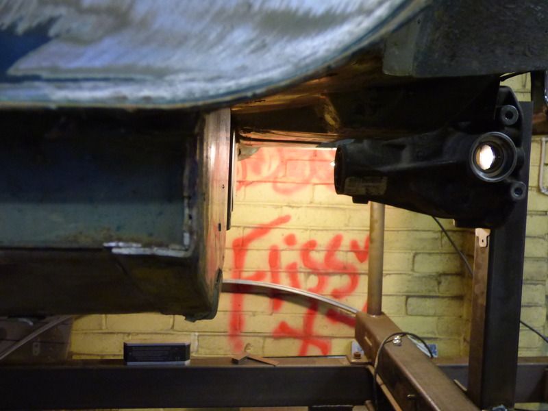
From which car is that diff, it looks quite chunky. Can that be a offroader diff??? looks like it....please tell me that is not true....
Even the one on my 450hp BMW 1M seem to be smaller.
Would try to use a different much smaller one, e.g.. BMW E30 325ix. Quite small with 40% LSD and just block of the front output for the front wheels as this is a 4 wheeler diff. Another small and cheap alternative would be the rear diff from the Suzuki Swift 4x4, has also an LSD but I don't know the specs. Both will be handling the torque from the turbo R1 without an issue, the 325ix diff I had in my e30 V8 with 260hp and 400nm torque with just a separate oil cooler for the diff oil.
The 4 wheel drive conversion with the honda uses the old civic shuttle (EE4) diff but could be near the limit of it with only rwd.
These are all diffs with a LSD from OEM, you could use also a widely used RWD diff where you fit an aftermarket LSD. Also here E30 325 Diff or the E36 325i ones you can get cheap and a good variety of LSD for a good price.
Edited by Helldriver, 31 May 2015 - 11:12 PM.
#233

Posted 01 June 2015 - 08:09 AM
Er...
FWD: Very poor traction, rearward weight transfer unloads your driving wheels. Torque steer always a problem and you've got very little room in the front anyway.
4WD: Loads of additional weight and complexity. Also you'll never make enough torque with a bike engine to use all the traction.
RWD: Slight weight penalty, best traction and weight distribution.
All the BEC boys are on a freelander diff. They weight less than the sierra and they're common and very cheap. LSD's are available if you want one.
Everyone has their view, this is the internet you're all entitled to it of course!
#234

Posted 01 June 2015 - 08:24 AM
I, for one, am just glad to see you're back on track......and look forward to more updates.
#235

Posted 01 June 2015 - 08:41 AM
Anyway spent an hour last night.... Mostly sweeping dust off it ![]()
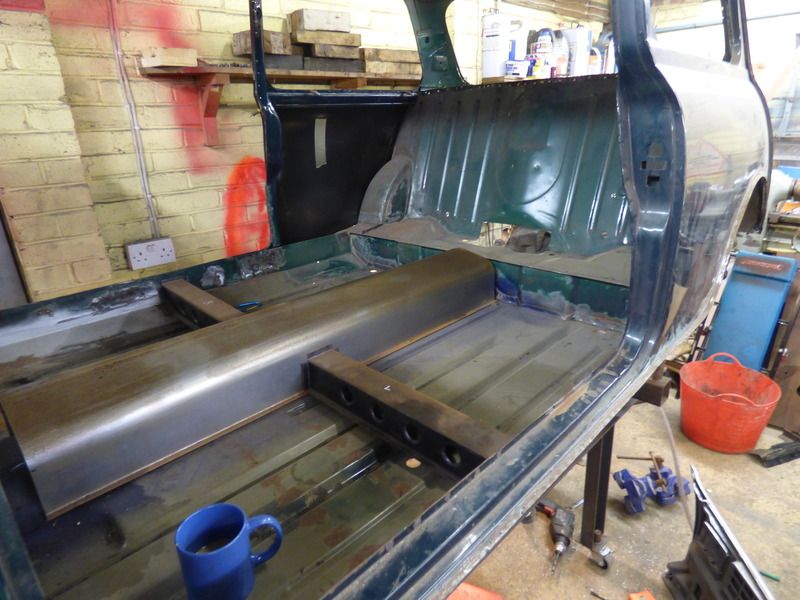
Looking forward to building in the tunnel and centre cross member structure. Its got to carry the centre diff mounting, so important to get right and the first "real part" of the project when it comes to construction. Welded roll structure in after that too... Maybe in time for the 2020 world cup ![]()
#236

Posted 01 June 2015 - 08:52 AM
Interesting project, will be watching out for updates, good job!
#237

Posted 01 June 2015 - 09:29 PM
Er...
FWD: Very poor traction, rearward weight transfer unloads your driving wheels. Torque steer always a problem and you've got very little room in the front anyway.
4WD: Loads of additional weight and complexity. Also you'll never make enough torque with a bike engine to use all the traction.
RWD: Slight weight penalty, best traction and weight distribution.
All the BEC boys are on a freelander diff. They weight less than the sierra and they're common and very cheap. LSD's are available if you want one.
Everyone has their view, this is the internet you're all entitled to it of course!
sure and it is good that someone like you just try things a lot guys said not possible. know that well, everybody said a BMW 750i 12 cylinder doesn't fit in a E30, proofed that they are wrong.....
what you are saying about FWD and RWD is true regarding straight acceleration but not for curves, where the mins strength are with short wheelbase and wheels at the edges. In curves the FWD is better for the mini as it pulls the car through the curve.
So it is up to usage of the car and the concept which is better for you.
regarding Torque steer hardy spicer and same length drive shafts are working solutions and traction of a soft slick is enough too.
AWD doesn't add so much weight and it is low down, with the unfavorable weight limits in today's racing for the mini where it is too light anyhow this brings the best added weight solution&traction under all conditions you can get. Total weight is not the best criteria...
An awd forced induction mini bec with 50:50 static weight distribution would be the fastest one you could build. one engine front and one back, both forced inductions would be the ultimate weapon....
Edited by Helldriver, 01 June 2015 - 09:33 PM.
#238

Posted 05 June 2015 - 06:20 PM
Thank you for proofing it!
#239

Posted 05 June 2015 - 06:38 PM
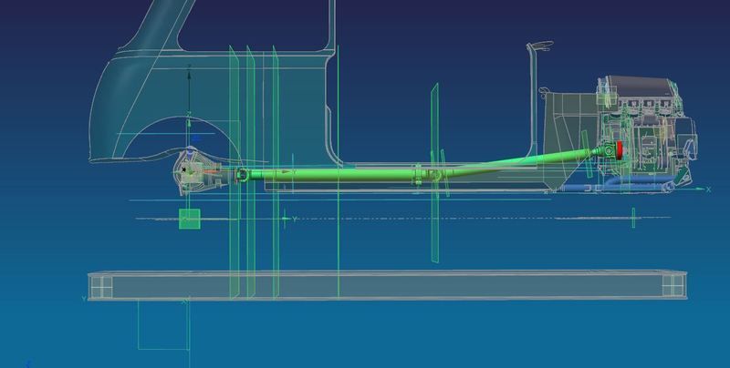
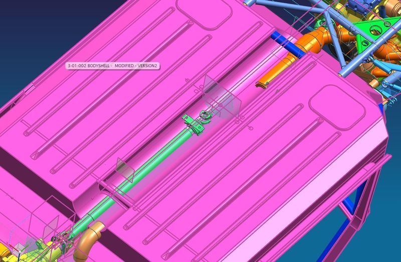
Been preparing the manufacturing spec for the prop shaft, which is a great candidate for myfirst joyous bubble-wrapped package arrival on this job! I need to send off a proposal to Bailey Morris once I've got all the info ready. "Earlier in this thread" I phoned them and talked though the prop design with them. The notes I took are what I designed the current one to, mostly regarding centre joint position and that kind of thing, so hopefully this will be straightforward.
There's not a lot to show really - the last CAD picture kind of covers it. Just doing the donkey work of filling in their "request for quotation" form etc.
I think next steps are to get the prop, and look to either a) mount the mock-up engine on the jig with the propshaft flange on it.. or b) make a new bit of the jig to bolt the prop flange directly to at the engine end.
One of the key potential trouble areas in the design as I see it at the moment is the prop joint mount in the middle of the floor. With two people in the car, and some decently aggressive gear cuts, that centre joint is going to be hanging out in the middle of nowhere structurally. Going this way I can build the prop into the car before the tube structure goes in - meaning I can modify the deign if it doesn't look or feel strong enough in the centre of the floor. You want to take your time and get it right ![]()
![]()
![]()
![]()
![]()
![]()
1 user(s) are reading this topic
0 members, 1 guests, 0 anonymous users


