
After destroying the first remote oil filter take-off, I was a bit more careful with this second one. You can just see on the top where I ground away a tiny bit of material to clear protruding areas of the R1's engine block. I also had to machine down the R1's oil filter bolt head some.

Now it's really time to install the engine.

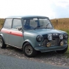
A tight fit in back. Here you can also see the engine ground strap I installed.

Don't ever paint parts before test-installing them. Total waste of time. The drive shafts I painted black a month ago look even worse now than they do in the photo. It won't be a problem though as you'll see at a later date.

The rear engine steady mount is now installed.

The photo is out of focus, but you can see that the engine did clear the location I picked out for the brake union 4-way. I finished installing the lines coming back from the left and right front wheels.

I jacked the car up to gain access to this fitting on the underside of the transfer box. This line routes around to the righthand side of the engine bay and thru a thermostat switch and oil filter before connected onto the oil pump.

After WAY too much work, the driveshafts are installed.

Time to fill and bleed the hydraulic clutch system. Result? It works great. Bad news is the clutch itself does not. The '02-'03 R1 clutch mechanism is notoriously easy to screw up on installation. I suspected I did it wrong but wasn't able to test it easily outside the car. Guess I'll be pulling the motor one more time before startup.

Here is the transfer box oil cooler sans lefthand mounting ears. This is one of the smallest oil coolers offered and in the Mini engine bay it is still too big. With some more trimming and a custom mount, it should work.

Speaking of custom mounts, here is what I came up with. I start with a bolt, washer, and a couple nuts. I then weld the nut to the washer, and then weld the washer to a short length of steel pipe.


End result? A removeable column to support the oil cooler bracket.

This is the oil cooler mount I quickly fabbed up.

I'm not finished but it looks like it will work. I can finish it once I get the exhaust back from the ceramic coaters.

Here is another line I made for the transfer box cooling system. This is looking down the righthand side of the engine bay at the Tilton oil pump. The blue canister is an in-line oil filter. The device below that is a temperature-activated switch, which will only turn the pump on when oil temperature exceeds 180F.

My first attempts at fabricating a bracket for the clutch and brake fluid reservoirs did not go well. In fact, it turned out awful. I really need a few additional tools to do it right but these would be quite expensive and take up too much space. I also didn't feel like running to Techshop to make what I needed. I decided to try and work with something I had already in the garage. That is when I spotted the two Setrab oil cooler mounts. I purchased these with the cooler but I could not use them, despite my best efforts. Shame to waste them though. So with a few modifications they work quite well.

This is how she looks at the moment. Of the 5 systems I have to finish ( the cooling system, remote oil filter system, transfer box cooling system, exhaust system, and electrical system) I have now completed.....none. However, I have made progress on every item. Check back soon for another update.
More soon...
Edited by Joe250, 25 May 2010 - 01:50 AM.


.jpg)