


1962 Mk1 Rebuild
Started by
Joe250
, Jul 21 2008 07:55 PM
374 replies to this topic
#76

Saxo-Fiesta-Mini
-

- Members
-

- 2,889 posts
Up Into Fourth
- Local Club: LCMOC
Posted 25 March 2009 - 07:07 PM
looking nice i like the progress
#77
irishdude
-

- Noobies
-
- 124 posts
Mini Mad
Posted 28 March 2009 - 06:09 AM
Keep up the good work, really look good
#78
Joe250
-
- Just Joined
-
- 215 posts
Mini Mad
- Location: California
Posted 29 April 2009 - 12:11 AM
Some more progress on my Mk1. I now have the pedals in the car along with the steering column. These two bits took so much time because they are somewhat custom and also due to the fact that they had to be placed very precisely in the car using a custom mounting solution. I'm new to this so it took a lot of thinking, measuring and of course mistakes.


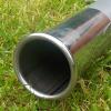
I started with 2 original steering columns, cut the tops off of them and combined them with a length of steel tube.

I fabricated a bracket out of aluminum using a mill. I enjoyed it but it is very time consuming.


Here is the column I made.

And here are all the various pieces that replace the stock column and mounting bracket.

Here it is fitted into the car. It sure extends back a ways. You can also see the pedals mounted up in this shot.

I was just barely able to fit my brake pedal to the left of the column and still re-angle the column to the left to get the steering wheel centered with the driver. This should facilitate left-foot braking and still allow use of the clutch when needed.
With the pedals mounted further to the right, the accelerator pedal was going to need some serious reworking to get it in position. It seemed much easier at this point to purchase an aftermarket item. I did an internet search and found this replacement. Something about it just compelled me to purchase it:

Joe
I started with 2 original steering columns, cut the tops off of them and combined them with a length of steel tube.
I fabricated a bracket out of aluminum using a mill. I enjoyed it but it is very time consuming.
Here is the column I made.
And here are all the various pieces that replace the stock column and mounting bracket.
Here it is fitted into the car. It sure extends back a ways. You can also see the pedals mounted up in this shot.
I was just barely able to fit my brake pedal to the left of the column and still re-angle the column to the left to get the steering wheel centered with the driver. This should facilitate left-foot braking and still allow use of the clutch when needed.
With the pedals mounted further to the right, the accelerator pedal was going to need some serious reworking to get it in position. It seemed much easier at this point to purchase an aftermarket item. I did an internet search and found this replacement. Something about it just compelled me to purchase it:
Joe
#79
carboy001
-
- TMF+ Member
-
- 1,065 posts
One Carb Or Two?
Posted 29 April 2009 - 12:19 AM
That setup is just immense! 
Loving the custom work, congrats to your good self
Loving the custom work, congrats to your good self
#80
Deathrow
-
- TMF IT Specialist
-
- 5,734 posts
Have you tried turning it off and on again?
- Name: Adam
- Location: Manchester, UK
Posted 01 May 2009 - 04:09 PM
Your custom steering column is fantastic! Very impressive indeed.
Not quite sure how your accelerator pedal will work though?
Not quite sure how your accelerator pedal will work though?
Edited by Deathrow, 01 May 2009 - 04:09 PM.
#81
feybrand
-
- Members
-
- 1,247 posts
One Carb Or Two?
- Location: Rugeley
Posted 01 May 2009 - 04:50 PM
thats impressive
#82
Joe250
-
- Just Joined
-
- 215 posts
Mini Mad
- Location: California
Posted 01 May 2009 - 06:02 PM
Not quite sure how your accelerator pedal will work though?
Why? Because it is push instead of pull? I've already thought of that. I'm going to set the engine to idle at wide open throttle, then I'll just push the throttle pedal down when I want to drop the revs.

Actually, I purchased this along with the pedal:
http://www.joesracin...p?idproduct=793
Edited by Joe250, 01 May 2009 - 06:03 PM.
#83
tedmcedd
-
- Traders
-
- 2,751 posts
Up Into Fourth
- Location: Huddersfield
Posted 01 May 2009 - 07:06 PM
that is immense!! i love it!
keep those updates coming!! hope they are all gonna be like this!
keep those updates coming!! hope they are all gonna be like this!
#84
Down&Out
-
- Traders
-
- 4,851 posts
The King Of Retro Cool
- Location: -
Posted 02 May 2009 - 09:17 AM
I've never really read this thread before, but i will say now this is my favourite mini on the forum. Its easily the best racer mini on the forum too! and im not usually a fan of racer minis
Great work, keep it coming .
.
Great work, keep it coming
.
#85
Joe250
-
- Just Joined
-
- 215 posts
Mini Mad
- Location: California
Posted 31 May 2009 - 08:47 AM
Lots of progress:

Lower dash is now back in.

Parking brake system is in and functioning.


New brake line brackets fabricated and installed.


Rear brake lines in.

Time to mount the R1 dash.


Rear brake pressure regulator installed. Should be out of the way here but still accessible.

A fellow Mini owner stopped by to hang out and talk shop. He took me for a quick spin. What a blast.
More updates very soon.
Lower dash is now back in.
Parking brake system is in and functioning.
New brake line brackets fabricated and installed.
Rear brake lines in.
Time to mount the R1 dash.
Rear brake pressure regulator installed. Should be out of the way here but still accessible.
A fellow Mini owner stopped by to hang out and talk shop. He took me for a quick spin. What a blast.
More updates very soon.
#86
Joe250
-
- Just Joined
-
- 215 posts
Mini Mad
- Location: California
Posted 01 June 2009 - 05:50 PM
As promised, here are some more updates:
The doors are now repaired and re-skinned. They'll need some adjustment to get the gaps better aligned but I think I'll wait for my friend to assist me. He always seems to know the right way to do stuff like that.


Simon hooked me up with all the hardware I needed for the doors.


This spare hood became my practise piece for MIG welding.

Once I got confident, I welded the door bins back on. How can you have a MK1 Mini and not have door bins?!


The doors are now repaired and re-skinned. They'll need some adjustment to get the gaps better aligned but I think I'll wait for my friend to assist me. He always seems to know the right way to do stuff like that.
Simon hooked me up with all the hardware I needed for the doors.
This spare hood became my practise piece for MIG welding.
Once I got confident, I welded the door bins back on. How can you have a MK1 Mini and not have door bins?!
#87
Joe250
-
- Just Joined
-
- 215 posts
Mini Mad
- Location: California
Posted 01 June 2009 - 05:56 PM
I made a small bracket to attach the tank retention straps, so the tank is finally in. I had planned on fitting the fuel pump out of a later fuel injected Mini but was just informed that I either have to purchase an FI-type tank or have someone weld in a custom bracket. Not sure what I'm going to do. Just one more thing to deal with.


The driver's side floor plate is now installed along with the throttle pedal.
The driver's side floor plate is now installed along with the throttle pedal.
#88
Joe250
-
- Just Joined
-
- 215 posts
Mini Mad
- Location: California
Posted 01 June 2009 - 06:09 PM

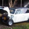
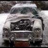
A previous owner grafted this...thing onto the nose of the Mini. As best as I can tell, it was going to have a hole cut into it and an oil cooler mounted behind it. Although I will probably run one, if not two oil coolers, I still didn't want this lump on my car. They also removed the attachment point for the front bumper while they were at it. So now it was time to undo these changes. I purchased a new front body panel but there really was no need to go through the trouble of cutting the entire front panel off and welding a new one on. Better just to graft in the sections I really needed.


I cleaned up the hole left behind and then marked the same area of the new front panel. I cut out a little extra to ensure I could grind it down to a tight fit in the car. Remember how much trouble I had butt welding panels with a large gap between them? To make life as easy as possible when I started welding, I really took my time here and got the panels to align almost perfectly. Besides the rectangular panel, I also took the bumper attachment flange and the two reinforcement brackets/license plate mounting flanges.

Finally the new panel aligns with the front panel.

Ready for welding.


It still needs some grinding but it is getting there.

It was now time to attach the bumper support flange. Everything was sprayed with weld-through primer and then plug welded into place. I would have used my trusty spot welder but the panels were not accessible with the tongs I have. I'll have to order some with a wider opening.

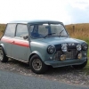
With the flange in place, the bumper pops right on. Clearance is tight but the ends just clear the fender flares.
While I had the welder out I decided to knock another small item off my to-do list. With my current front suspension settings (lowered, more negative camber) there isn't enough adjustment in the trackrods to undo a massive amount of toe-out. David Vizard's book mentions a fix. Besides installing the longer Triumph Spitfire trackrods, which I'd already done, he suggested welding a nut onto the end of the trackrods to provide just enough additional threads to work. I decided to give it a try. Has anyone done this or heard anything about it, good or bad? I think this car will see some serious corner loading over the years and I'd like to have full confidence in the steering system.


#89
obiwan riley
-

- Noobies
-
- 76 posts
Stage One Kit Fitted
Posted 01 June 2009 - 06:37 PM
got to admire your work there joe
fine project! nice to see it on the road![=]](https://www.theminiforum.co.uk/forums/public/style_emoticons/default/proud.gif)
fine project! nice to see it on the road
#90
zebidee
-
- Members
-
- 444 posts
Speeding Along Now
Posted 01 June 2009 - 10:36 PM
This is a truly brilliant build! Love the detail going in to it!


1 user(s) are reading this topic
0 members, 1 guests, 0 anonymous users


