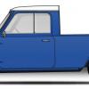
Holy crap this is insane! So much talent here. Muchos respect. LOVE the car.

1962 Mk1 Rebuild
#271

Posted 03 January 2014 - 09:12 PM
#272

Posted 04 January 2014 - 01:15 AM
just read from start to finish and was a great read some really great ideas here and is it near completion?
Dan
#273

Posted 05 January 2014 - 07:10 AM
Thanks for the kind words. I'm on holiday at the moment. The project was also set back when a (motorsport wiring) parts supplier stiffed me. I hope to have some updates before the end of this month.
#274

Posted 05 January 2014 - 12:12 PM
http://joe250.com/ca...58/IMG_8980.jpg
joe what length are these please done a similar thing with my mini however going to make some i like the look of these. cheers matt
#275

Posted 22 January 2014 - 01:14 AM
http://joe250.com/ca...58/IMG_8980.jpg
joe what length are these please done a similar thing with my mini however going to make some i like the look of these. cheers matt
The long sides of the triangle are 12" long.
#276

Posted 22 January 2014 - 10:16 PM
The long sides of the triangle are 12" long.http://joe250.com/ca...58/IMG_8980.jpg
joe what length are these please done a similar thing with my mini however going to make some i like the look of these. cheers matt
Thanks joe that's great
#277

Posted 23 January 2014 - 07:18 PM
I hope to have some updates before the end of this month.
Roll on with the updates Joe!
#278

Posted 02 February 2014 - 09:17 PM
Great build!
#279

Posted 03 March 2014 - 08:06 PM
I have nothing more than excuses to offer at the moment. The Mini has gone untouched for the past 4 months. Thankfully that changed yesterday when I finally dragged myself back out to the garage and resumed work on the wiring. It was quite frustrating trying to recall exactly what I was doing when I last walked away but after a few hours I was back in the swing of things. I hope to show some progress here soon.
In the meantime, here is one of the places I visited while on vacation: http://minimaruyama.co.jp/
This Mini shop in Tokyo is quite impressive - the cars, the building, the variety of parts, and the owner, Mr. Maruyama. He was kind enough to give me a very thorough tour of his showroom.


This reminds me of something but I just can't put my finger on it.

According to Mr. Maruyama, this Mini is the same one pictured in the photo showing Stirling Moss racing it somewhere in the U.K.

If any of you find yourself in Tokyo with some time to kill, Mini Maruyama is well worth the effort.
#280

Posted 19 March 2014 - 12:52 AM
Finally! A real update.

After much debate and research I finally purchased a set of GoJaks. These things are great and I should have bought them a long time ago. As you step down on the grey foot pedal the sides of the jack ratchet inwards, picking the wheel and tire up off the ground. With all four wheels in the air you can roll the car around the garage quickly and easily.

Whichever end of the car that I will be working on will get rotated closest to the work bench.

This is a 14-pin connector I picked up for the upper instrument panel.

I've been trying to follow best-practices when wiring these connectors. Installers will put a service loop, a small coil in the wire, before inserting the wire into the back of the connector. This acts as a strain relief and leaves some spare wire should you have to go back later and correct a crimp. As you can see above I havne't quite got it down yet. I will keep at it.

Here you can see the completed wiring exiting the rear of the upper instrument console. I really want to re-make the entire console and clean it up but that will have to wait. For now I just want to get the Mini running on the street.

Here is another issue that just seems to have no end. I've installed a brake light switch next to the rear brake pressure limiter valve. I have carefully matched the various threads and plumbing standards but I keep getting leaks. I'll figure it out in another 2 or 3 gallons of brake fluid, I'm sure.

Here are the sub-harnesses for the RH headlight and the RH turn signal. Other than being aimed, the headlights are basically done now.

Here is where the headlight/turn signal wiring enters the engine bay.

What a mess! It only gets more crowded every day. I've got to find a place to install two relay/fuse boxes somewhere in here.

In studying up about car wiring I found numerous mentions of the problems created by poor grounds. It is easy to overlook the ground side of the circuit since so much focus is placed on the power side but they are equally important. ThereforeI decided to install a few dedicated ground points throughout the car. Here is one in the engine bay.

From another perspective.

Here you can see another ground point I've attached to the front wall of the boot. I will be using this to ground the battery. You can also see some of the other wires I've installed to finish out the taillights, brake lights, license plate light, fuel pump, and fuel level sender. It will all be routed nicely once I can test fit the fuel tanks.

I finally started routing wires from the boot, up the C-pillar and along the roof gutter towards the front of the car.

Here is where the wiring exits the A-pillar. This RH side of the dash is where I will be locating two more relay/fuse boxes, hence the wires all ending up here.

After relocating the blipper controller I was able to finally install the relay/fuse boxes on the firewall. This should keep them out of trouble but keep them reasonably accessible once the bonnet is installed.

In this photo you can also see how the ignition coil and sensor wiring turned out.
Still lots to do....
Edited by Joe250, 19 March 2014 - 12:55 AM.
#281

Posted 19 March 2014 - 07:39 AM
That is one looovely build. I'm really quite jealous of your wiring, I'm having a nightmare with mine! ![]()
#282

Posted 20 March 2014 - 09:41 AM
everything is just so neat and precisie!
#283

Posted 30 March 2014 - 01:55 AM

I originally designed the wiring system with two fuse/relay boxes inside the engine compartment. I would have preferred mounting them in the passenger compartment to keep them away from the heat and the elements that they would be exposed to within the engine bay. Plus the main ECU, sub-ECU's (Pro-Shift, PowerCommander, etc.) and any number of switches, gauges, and controls are inside the passenger compartment. Better to keep the wiring run as short and simple as possible. Two problems arose with this plan - one was that I would need to pass a large number of wires back and forth through the firewall to connect everything within the passenger compartment to the fuse/relay boxes. The second was that given the fuse/relay boxes I had already decided upon, I was quickly running out of circuits to have everything fit into just two boxes.
I finally decided to double the number of fuse/relay boxes and mount two in the passenger compartment and two within the engine bay. One of each would be constantly connected to power, the other would be switched power (meaning powered up only when the ignition key was in either the 'ACC' or 'On' position). In order to get power to the two boxes in the passenger compartment I mounted these two red pass-thru connectors on the firewall. I will soon hook up wires from the power relay modules two outputs.

The power will flow through to the backside of the firewall and then land at either of the fuse/relay boxes.

The next challenge was to find a suitable location for the interior fuse/relay boxes and a way to mount them. Underneath the lower dashboard might have been a good choice had I not already decided to mount the R1 ECU and sub-ECU's there. Instead the boxes would need to mount on the dashboard, facing the passenger. This would be similar to how the factory Mini Works rally cars did it, but instead of using sheetmetal I decided to go with carbon fiber.

I thought trimming carbon fiber required special tools and techniques but apparently not. I watched this helpful video which recommended using any number of conventional hand and power tools. It sounded similar to working with fiberglass, just more expensive if you screw up.

I used blue painters tape to both protect the nice finish on the carbon fiber sheet as well as give me a place to mark out the dimensions of the mounting holes and panel pass-thru holes.

I decided to use these quick-release pip pins to make removal of the panel as quick and easy as possible.

This is how the fuse/relay boxes look installed in the panel. Now it was time to find a suitable mounting method onto the dashboard.

Finding the best location took a bit of time.

Once I had the location I was able to work backwards and fabricate a mounting bracket. Here it is completed and painted.

And here is how everything looks mounted in the car.


Soon I will be able to terminate a number of the wires you see here into the back of the fuse/relay panels. One day I might even be able to start this car. Just imagine that!
Edited by Joe250, 30 March 2014 - 01:56 AM.
#284

Posted 31 March 2014 - 10:18 AM
Re your 'leaky' brake line, try some engineering blue on the taper seats, i had a similar problem to this at work and it turnout (after hours of messing around) that the female taper wasn't concentric to the tapped hole, not an obvious problem as you'd assume they are machined in the same set up, but it ment that the taper only seated on one side. hence the leak.
Just a possiblity, but looking at the thread i can't for one minute think you've made a basic error.
hope this helps.
#285

Posted 31 March 2014 - 04:25 PM
What?! This whole project is a basic error! ![]()
You make a good point though - I am assuming that the parts in question were manufactured 100% correctly. Sadly, that isn't always the case. I will re-examine both pieces involved before I spend any more time on it. Cheers!
2 user(s) are reading this topic
0 members, 2 guests, 0 anonymous users


