ah I see. Great idea, sounded pretty good in the video, I'm guessing you had the valve open!


1962 Mk1 Rebuild
Started by
Joe250
, Jul 21 2008 07:55 PM
374 replies to this topic
#226

freshairmini
-
- Members
-

- 1,718 posts
Camshaft & Stage Two Head
- Location: Alresford, Hampshire
- Local Club: Winchester Area Mini Owners
Posted 11 December 2012 - 04:31 PM
#227
tedmcedd
-
- Traders
-
- 2,751 posts
Up Into Fourth
- Location: Huddersfield
Posted 13 December 2012 - 08:36 PM
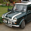
The paint looks incredible! Love the cooper stripe! The shell is top!
The rebuild looks great. Nice detail going into it!
Great to see its still progressing!
Ed
The rebuild looks great. Nice detail going into it!
Great to see its still progressing!
Ed
#228
Joe250
-
- Just Joined
-
- 215 posts
Mini Mad
- Location: California
Posted 01 January 2013 - 08:11 AM
There isn't a lot of visible progress. I've spent a considerable amount of time working on things that just don't seem like much or aren't visible. Things like rust-proofing hard-to-reach areas. Minis are full of them. I've also got a number of holes that either were there when I bought the car or that I drilled for some unknown reason, and they need filling.

Progress! The rear bumper is on.

The taillights are in.

The door cards and door bin liners are installed. If I ever need to install Mk1 door cards again I will sawzall the door skins off to make room, then repair all the damage. It truly would be easier than any other conceivable method. Pure hell.

This is the start of the sixth take on seat brackets. Yes, sixth. Getting the seat exactly positioned and with mounts that are up to the task has taken a while. I think I've got it figured out this time.

The pedal cage is in and although just as ugly as before, it is far more secure. It took lots of time but I've managed to bolt the cage to the front bulkhead. I am hoping the entire assembly will have less flex than before. I'll know once the brake system is complete. I'm also working on installing my throttle pivot.

Here you can see I'm working on getting the fuel tanks installed and setup.

This shot shows the rough, matte finish of the LizardSkin coating. It really needs to be covered as it isn't very abrasion resistant. I'm looking into my options there.
You can also see the backside of the fiberglass cover I made for the rear seatback. The cardboard cover that is normally there aren't readily available. Now I just need to paint this one.
I've also installed the battery bulkhead connector. More on that later.

I've test-fit the seats. I think they are going to work.

Here is a terrible photo of one of the seat rail mounts. I'll try to get some better photos later, perhaps after they are powdercoated.

I am only test-fitting the floor plates and throttle pedal here but I'm getting close.

This photo shows three things - I've opened up a D-shaped hole on the passenger side of the front panel to match the one on the driver's side. The original is to assist with extracting hot air from the radiator out of the LF wheelwell. I don't know why I wouldn't want additional cooling for the brakes on the passenger side so there you have it. Of course after I finished I held up the front grille and the way it is built it completely blocks the holes on both sides! I'll be trimming that next I suppose.
I've also re-opened the hole on the driver's side of the firewall. The steering brace clamp cannot fit onto the rollcage and still clear the firewall so something had to give. I'll work on closing this hole back up with a blister shaped piece of sheetmetal soon.
Finally, you will notice the black bolt jutting out of the bulkhead. That is one of the new mounting points for the pedal cage.


Here I've test-fit the rear subframe and exhaust while I begin sorting out the new rigid fuel lines that I am about to install. I've already begun compiling a new list of fittings I need to order. I've had to choose between mounting the fuel lines inside the passenger compartment (something I seen done quite frequently but that I will never consider), running them in the exhaust tunnel or hanging beneath the passenger floor. Although I run the risk of passing too much heat from the exhaust to the fuel I have decided the lines will go in the tunnel. I'd rather work around any heat issues than run the risk of the lines being crushed or ripped open by California's rapidly-deteriorating and trash-strewn roads.

I've also mounted the rear coilovers. Just another tiny piece of the puzzle.
Progress! The rear bumper is on.
The taillights are in.
The door cards and door bin liners are installed. If I ever need to install Mk1 door cards again I will sawzall the door skins off to make room, then repair all the damage. It truly would be easier than any other conceivable method. Pure hell.
This is the start of the sixth take on seat brackets. Yes, sixth. Getting the seat exactly positioned and with mounts that are up to the task has taken a while. I think I've got it figured out this time.
The pedal cage is in and although just as ugly as before, it is far more secure. It took lots of time but I've managed to bolt the cage to the front bulkhead. I am hoping the entire assembly will have less flex than before. I'll know once the brake system is complete. I'm also working on installing my throttle pivot.
Here you can see I'm working on getting the fuel tanks installed and setup.
This shot shows the rough, matte finish of the LizardSkin coating. It really needs to be covered as it isn't very abrasion resistant. I'm looking into my options there.
You can also see the backside of the fiberglass cover I made for the rear seatback. The cardboard cover that is normally there aren't readily available. Now I just need to paint this one.
I've also installed the battery bulkhead connector. More on that later.
I've test-fit the seats. I think they are going to work.
Here is a terrible photo of one of the seat rail mounts. I'll try to get some better photos later, perhaps after they are powdercoated.
I am only test-fitting the floor plates and throttle pedal here but I'm getting close.
This photo shows three things - I've opened up a D-shaped hole on the passenger side of the front panel to match the one on the driver's side. The original is to assist with extracting hot air from the radiator out of the LF wheelwell. I don't know why I wouldn't want additional cooling for the brakes on the passenger side so there you have it. Of course after I finished I held up the front grille and the way it is built it completely blocks the holes on both sides! I'll be trimming that next I suppose.
I've also re-opened the hole on the driver's side of the firewall. The steering brace clamp cannot fit onto the rollcage and still clear the firewall so something had to give. I'll work on closing this hole back up with a blister shaped piece of sheetmetal soon.
Finally, you will notice the black bolt jutting out of the bulkhead. That is one of the new mounting points for the pedal cage.
Here I've test-fit the rear subframe and exhaust while I begin sorting out the new rigid fuel lines that I am about to install. I've already begun compiling a new list of fittings I need to order. I've had to choose between mounting the fuel lines inside the passenger compartment (something I seen done quite frequently but that I will never consider), running them in the exhaust tunnel or hanging beneath the passenger floor. Although I run the risk of passing too much heat from the exhaust to the fuel I have decided the lines will go in the tunnel. I'd rather work around any heat issues than run the risk of the lines being crushed or ripped open by California's rapidly-deteriorating and trash-strewn roads.
I've also mounted the rear coilovers. Just another tiny piece of the puzzle.
Edited by Joe250, 01 January 2013 - 08:13 AM.
#229
mk1leg
-

- Members
-
- 9,343 posts
Crazy About Mini's
- Location: Jersey
- Local Club: Mini Club Jersey, MCR
Posted 01 January 2013 - 10:59 AM
Well what can I say this is an amazing rebuild and your skills are just as..........we want more Vids ..... 
#230
Joe250
-
- Just Joined
-
- 215 posts
Mini Mad
- Location: California
Posted 11 February 2013 - 05:40 AM
Extra hours at work and illness have set the build back quite a bit in the new year. Frustrating but I make progress whenever I can.
I made the decision very shortly before the body went off to paint to install a righthand fuel tank in the boot. Nick was kind enough to install the tank mounting straps but I still needed to modify the RH tank to be able to connect to the LH tank. I also needed a threaded insert welded onto the filler neck to fit the Aston-style cap. This required the services of my favorite welder.

Welding brass to steel? I left this to an expert.

Here I have marked the location of where I would like the steel AN fitting welded to the RH tank. A line will run from this fitting to a similar one mounted low on the LH tank.
With both fuel tanks finished, the next step was to connect them together and finish the fuel lines within the boot. There are 3 lines - the first carries fuel out of the LH tank via the in-tank fuel pump.

After passing through a quick-release connector, the fuel immediately passes through a filter then to a bulkhead connector in the boot floor. The second line is a return line from the engine.

Any unused fuel from the engine is returned back to the LH tank. The third, smaller line (not visible here) connects the LH and RH tanks together. There are two additional vent lines, one per tank. These have a one-way valve (the red piece) installed - air can be sucked in but no fuel can leak out. If instead the tanks become overpressurized the filler caps each have a spring-loaded release valve built in.

Here you can see the bulkhead fittings protruding underneath the boot floor.
The original plan was to run flexible stainless steel fuel lines under the car. I then convinced myselft to run rigid stainless steel lines instead. After attempting to make some complex bends without the benefit of the right tool, I realized a combination of the flexible and rigid lines might be best.


Here you can see the rigid lines run up the side of the exhaust tunnel. Since the exhaust will be running directly alongside the lines I am using an insulation by DEI. To help insulate the cabin from the exhaust I installed another product from DEI. This is a moldable, adhesive-backed aluminum/fiberglass sheet, visible in the photos above
The next big step in the project is getting a number of items powdercoated. This includes the front and rear subframes and the fuel tanks. Before I can start that process I need to do a little more test fitting and fabrication. The first thing to do was to put the engine back into the car.

Before the car was painted the method I used was to install the front subframe from underneath the engine bay, then use the engine hoist to drop the engine and engine cradle in from the top and bolt the two together. The engine is a tight fit and led to some scratches here and there back when the shell was just primered. Now that the car is painted, I decided on a different method. I bolted the engine to the subframe, slid it under the engine bay, then used the engine hoist to pull the whole entire assembly up into place. It worked reasonably well.
The first thing I tried once the engine was in place was installing the exhaust manifold. This was a nightmare the first time I tried it two years ago. I scratched the black ceramic coating off of the manifold and scratched the primer off of the bodywork in a few places. I am still trying to understand why but this time the manifold dropped right into place, an easy fit.

Next up was the fabrication of some brackets to hold the radiator in place. You may recall the incredibly ugly mount I made originally. Although it worked, it was not an elegant solution. The radiator came with mounting points already installed down the sides - a set of rivnuts in a pair of side rails. Why not utilize them?

The radiator is held in position pretty well by the top and bottom silicone hoses, so I think it will be enough to run just these two upper brackets. I can always add another set later.

With the change to the fuel lines I had to re-do them in the engine bay as well. Here they are plugged into the gold quick-release fittings. You can also see the inline fuel pressure gauge on the feed line. I installed it when I was first trying to fire up the engine and couldn't. It is a handy diagnostic tool so I decided to keep it installed. As long as it doesn't leak, it can't hurt, right?

This is where the lines drop down out of the engine bay and pass through the front subframe. I've mounted the lines in these aluminum brackets to keep them from rubbing against each other and anything else in the car. Braided SS lines are like hacksaws and over time can do a lot of damage if allowed to rub against anything. At the top of the photo you can see the fittings that wound up at the ends of these lines once trimmed to length.

The finished products.
With the engine in place and the diagonally-mounted slam panel braces, I can now see two things - the xfer box oil cooler is not going to get much air. The other is that there is almost nowhere to mount a custom intake air duct that I was considering fabricating. This would grab relatively cool air from just behind the front grille and send it into the side of the engine airbox. Neither of these issues are absolutely critical to getting the car running so I will likely come back to address them later on.
The oil cooler mount I fabricated two years ago is a sad mess. Time to make a cleaner, better version. More on that later....

I made the decision very shortly before the body went off to paint to install a righthand fuel tank in the boot. Nick was kind enough to install the tank mounting straps but I still needed to modify the RH tank to be able to connect to the LH tank. I also needed a threaded insert welded onto the filler neck to fit the Aston-style cap. This required the services of my favorite welder.
Welding brass to steel? I left this to an expert.
Here I have marked the location of where I would like the steel AN fitting welded to the RH tank. A line will run from this fitting to a similar one mounted low on the LH tank.
With both fuel tanks finished, the next step was to connect them together and finish the fuel lines within the boot. There are 3 lines - the first carries fuel out of the LH tank via the in-tank fuel pump.
After passing through a quick-release connector, the fuel immediately passes through a filter then to a bulkhead connector in the boot floor. The second line is a return line from the engine.
Any unused fuel from the engine is returned back to the LH tank. The third, smaller line (not visible here) connects the LH and RH tanks together. There are two additional vent lines, one per tank. These have a one-way valve (the red piece) installed - air can be sucked in but no fuel can leak out. If instead the tanks become overpressurized the filler caps each have a spring-loaded release valve built in.
Here you can see the bulkhead fittings protruding underneath the boot floor.
The original plan was to run flexible stainless steel fuel lines under the car. I then convinced myselft to run rigid stainless steel lines instead. After attempting to make some complex bends without the benefit of the right tool, I realized a combination of the flexible and rigid lines might be best.
Here you can see the rigid lines run up the side of the exhaust tunnel. Since the exhaust will be running directly alongside the lines I am using an insulation by DEI. To help insulate the cabin from the exhaust I installed another product from DEI. This is a moldable, adhesive-backed aluminum/fiberglass sheet, visible in the photos above
The next big step in the project is getting a number of items powdercoated. This includes the front and rear subframes and the fuel tanks. Before I can start that process I need to do a little more test fitting and fabrication. The first thing to do was to put the engine back into the car.
Before the car was painted the method I used was to install the front subframe from underneath the engine bay, then use the engine hoist to drop the engine and engine cradle in from the top and bolt the two together. The engine is a tight fit and led to some scratches here and there back when the shell was just primered. Now that the car is painted, I decided on a different method. I bolted the engine to the subframe, slid it under the engine bay, then used the engine hoist to pull the whole entire assembly up into place. It worked reasonably well.
The first thing I tried once the engine was in place was installing the exhaust manifold. This was a nightmare the first time I tried it two years ago. I scratched the black ceramic coating off of the manifold and scratched the primer off of the bodywork in a few places. I am still trying to understand why but this time the manifold dropped right into place, an easy fit.
Next up was the fabrication of some brackets to hold the radiator in place. You may recall the incredibly ugly mount I made originally. Although it worked, it was not an elegant solution. The radiator came with mounting points already installed down the sides - a set of rivnuts in a pair of side rails. Why not utilize them?
The radiator is held in position pretty well by the top and bottom silicone hoses, so I think it will be enough to run just these two upper brackets. I can always add another set later.
With the change to the fuel lines I had to re-do them in the engine bay as well. Here they are plugged into the gold quick-release fittings. You can also see the inline fuel pressure gauge on the feed line. I installed it when I was first trying to fire up the engine and couldn't. It is a handy diagnostic tool so I decided to keep it installed. As long as it doesn't leak, it can't hurt, right?
This is where the lines drop down out of the engine bay and pass through the front subframe. I've mounted the lines in these aluminum brackets to keep them from rubbing against each other and anything else in the car. Braided SS lines are like hacksaws and over time can do a lot of damage if allowed to rub against anything. At the top of the photo you can see the fittings that wound up at the ends of these lines once trimmed to length.
The finished products.
With the engine in place and the diagonally-mounted slam panel braces, I can now see two things - the xfer box oil cooler is not going to get much air. The other is that there is almost nowhere to mount a custom intake air duct that I was considering fabricating. This would grab relatively cool air from just behind the front grille and send it into the side of the engine airbox. Neither of these issues are absolutely critical to getting the car running so I will likely come back to address them later on.
The oil cooler mount I fabricated two years ago is a sad mess. Time to make a cleaner, better version. More on that later....
Edited by Joe250, 11 February 2013 - 05:41 AM.
#231
Willy_sa
-

- Noobies
-
- 93 posts
Stage One Kit Fitted
- Location: South Africa
- Local Club: MOCSA
Posted 11 February 2013 - 07:56 AM
Looks Great Joe!
#232
jonny f
-
- Members
-
- 1,485 posts
One Carb Or Two?
- Location: Surrey
- Local Club: Boxhill Mini Club
Posted 11 February 2013 - 01:23 PM
Looking good!
#233
Joe250
-
- Just Joined
-
- 215 posts
Mini Mad
- Location: California
Posted 28 March 2013 - 04:18 PM
Where I last left things, there were a number of items to fabricate and tweak before going off to powder coating. For those that do not know, powder coating is an alternative to painting. Both protect metal surfaces from the elements and enhance the appearance of parts but powder coating is a much more durable coating. It is almost impervious to chemicals and resists scratching and chipping. This makes it ideal for mechanical parts. Unlike paint, it cannot be touched up, so any holes that need drilling (or any other alteration that need to be made) should be done before coating. So that's what I did...

This is attempt number 2 for the oil cooler mount. Here you can see the hole flaring process begun.


What a neat tool. The hole allows the part to be lighter and the flare makes the panel stiffer. Win/win.

Here it is nearly complete. More photos when it returns from powder coating.

With the mount complete I could finally install the oil cooler.

Then I could locate and drill holes for the coolant overflow tank.

I installed rivnuts again for ease of install/removal.

And now I could focus on one final item in this corner of the engine bay - the transfer box' oil pump. Unlike during my earlier mock-up, this time I decided against mounting the pump directly to the inner fender. It is just too heavy. I spent a lot of time fabricating two different brackets and spent a few hours moving the pump into every conceivable angle and location - nothing worked well. I finally asked myself if it wouldn't be easier to use a smaller pump. A few hours on the web pointed me towards a better and smaller pump - the Weldon K9200-A.

That might not seem like a significant difference in size but when you dealing with a Mini engine bay, it is.

After finding a suitable mounting location and orientation I fabricated a mounting bracket.

I removed the two upper motor mount bolts....

...and ran them through the bracket.


Mounting clamp installed.

And finally I have the pump installed. There is one small consideration that I have to make for using a precision pump like this - a 40 micron filter before the pump and a 10 micron after. More on that plumbing nightmare soon.
This entire project would be greatly simplified if I skipped the xfer pump, oil cooler, thermostat, and all the custom lines, but if my sources are correct, the xfer box will also be the biggest potential weak spot of the entire car. Worse, it is also the item hardest to repair or replace. Not having to rely on a chain to transfer power from the R1 engine to the differential is one of the biggest factors that drew me to the MinieXvo kit. If all of this extra work keeps the xfer box happy then it is worth it.

With the new front subframe in place I attempted to mount the KAD front anti-roll bar. The reinforcements that Mondosport made to the subframe meant that a spacer was necessary to drop the ARB slightly. Easy enough. Because access was so difficult, after removing the subframe I welded the nuts to the top of the subframe to make install and removal of the bar a bit quicker and easier.

Here you can see the ARB as well as another bracket I fabricated. This will serve double duty as a license plate holder as well as a semi-concealed location for the Hella horns.


More photos of this bracket later.

Now on to the electrical quick-connectors. It suddenly occurred to me that I had not designed things properly for these connectors to work. If I was ever going to be able to remove the driver's compartment-side of the connection, I would have to enlarge the bulkhead holes and re-design my mounting plate.

Here is a cardboard template being used to mock things up.

The plate will continue to serve double duty - locating the connectors as well as forming the upper half of the engine steady.

At the top you can see the original plate I made. I continued to refine the design until I finally had a template that seemed perfect. I have learned the hard way what a time-saver templates can be. Finally I put that knowledge into practice.

A bit of cutting, welding, and grinding and here is the result.


The pile of parts ready for powdercoating continued to pile up.

Just out of curiosity I decided to test fit a front and rear wheel to check for fitment. As I feared the 10x5” Revolution wheel sticks proud of the bodywork a bit.


The front does too but a lot less. There is a reason most Minis are fitted with fender flares of some type. I am going to resist installing a set for now.
This is attempt number 2 for the oil cooler mount. Here you can see the hole flaring process begun.
What a neat tool. The hole allows the part to be lighter and the flare makes the panel stiffer. Win/win.
Here it is nearly complete. More photos when it returns from powder coating.
With the mount complete I could finally install the oil cooler.
Then I could locate and drill holes for the coolant overflow tank.
I installed rivnuts again for ease of install/removal.
And now I could focus on one final item in this corner of the engine bay - the transfer box' oil pump. Unlike during my earlier mock-up, this time I decided against mounting the pump directly to the inner fender. It is just too heavy. I spent a lot of time fabricating two different brackets and spent a few hours moving the pump into every conceivable angle and location - nothing worked well. I finally asked myself if it wouldn't be easier to use a smaller pump. A few hours on the web pointed me towards a better and smaller pump - the Weldon K9200-A.
That might not seem like a significant difference in size but when you dealing with a Mini engine bay, it is.
After finding a suitable mounting location and orientation I fabricated a mounting bracket.
I removed the two upper motor mount bolts....
...and ran them through the bracket.
Mounting clamp installed.
And finally I have the pump installed. There is one small consideration that I have to make for using a precision pump like this - a 40 micron filter before the pump and a 10 micron after. More on that plumbing nightmare soon.
This entire project would be greatly simplified if I skipped the xfer pump, oil cooler, thermostat, and all the custom lines, but if my sources are correct, the xfer box will also be the biggest potential weak spot of the entire car. Worse, it is also the item hardest to repair or replace. Not having to rely on a chain to transfer power from the R1 engine to the differential is one of the biggest factors that drew me to the MinieXvo kit. If all of this extra work keeps the xfer box happy then it is worth it.
With the new front subframe in place I attempted to mount the KAD front anti-roll bar. The reinforcements that Mondosport made to the subframe meant that a spacer was necessary to drop the ARB slightly. Easy enough. Because access was so difficult, after removing the subframe I welded the nuts to the top of the subframe to make install and removal of the bar a bit quicker and easier.
Here you can see the ARB as well as another bracket I fabricated. This will serve double duty as a license plate holder as well as a semi-concealed location for the Hella horns.
More photos of this bracket later.
Now on to the electrical quick-connectors. It suddenly occurred to me that I had not designed things properly for these connectors to work. If I was ever going to be able to remove the driver's compartment-side of the connection, I would have to enlarge the bulkhead holes and re-design my mounting plate.
Here is a cardboard template being used to mock things up.
The plate will continue to serve double duty - locating the connectors as well as forming the upper half of the engine steady.
At the top you can see the original plate I made. I continued to refine the design until I finally had a template that seemed perfect. I have learned the hard way what a time-saver templates can be. Finally I put that knowledge into practice.
A bit of cutting, welding, and grinding and here is the result.
The pile of parts ready for powdercoating continued to pile up.
Just out of curiosity I decided to test fit a front and rear wheel to check for fitment. As I feared the 10x5” Revolution wheel sticks proud of the bodywork a bit.
The front does too but a lot less. There is a reason most Minis are fitted with fender flares of some type. I am going to resist installing a set for now.
Edited by Joe250, 28 March 2013 - 04:26 PM.
#234
Joe250
-
- Just Joined
-
- 215 posts
Mini Mad
- Location: California
Posted 28 March 2013 - 04:23 PM

Nothing big but I was pleased with how this turned out. This is the little gear indicator mount I milled at Tech Shop. It just needed a bit of cleaning up prior to powdercoating.

A sanding block and some 400 grit sandpaper removed the machining marks and gave a nice consistent finish.

Here is one of the driver side seat brackets I fabricated: heavy, ugly, and poorly welded.

On to the battery box. I was about to fabricate some convoluted battery mount but wisely decided to just buy something. I found a nice aluminum side-mount bracket. It just required drilling some holes which I then touched up.


While at the hardware store I noticed some special washers with a galvanized bevel shape with a rubber washer on the backside. I used them here in an attempt to keep the elements out of the battery box.

Next items to prep - the jack stands. I decided to weld some feet onto them. Turned out decent I think.

Time to remove the engine again so I can do some final prep to both the front subframe and the MinieXvo subframe.

I have a sneaking suspicion the layout of these ECU's will have to change soon but for now these locations seemed best. I bolted, strapped and velcroed them to the mounting panel depending on their built-in mounting points, weight and size.

I am not really proud of the quality of my work but I definitely like this idea. I stole it from the Turbo Minis forum. For some stupid reason the holes in the sides of the Mini subframe are big enough for the driveshafts and outer CV joints but not the inner pot joints. Just a bit of trimming enlarges the standard holes to allow the complete assembly through. This means I won't have to try to strap the joint boots on whilst (I steal lots of stuff from the UK forums) installed. I am CHUFFED!

Another minor detail but one I almost overlooked. This tab is one I added to retain the clutch slave cylinder. If you think these welds are bad, you should have seen what was there originally.

I put off installing the KAD rear ARB until now because I knew I would have to do some crazy custom fabrication. Turns out I was wrong and right. The bar I have been staring at in the garage for over 4 years won't work at all. It is designed to bolt directly to the back of a standard rear subframe. My attempts to make it work on my car regardless went nowhere.
KAD to the rescue! They make a rear ARB for poor saps like me with abbreviated rear subframes (a weight-saving idea that only works when ditching the stock rubber donuts and going with coilovers). Just five days later (!) it was at my doorstep. It too would require some fabrication but not much. Here I am test fitting the bar in place while trying to follow KAD's advice - mount the bar as horizontal as possible with the drop links as vertical as possible. With the exhaust in place I was able to find a location that did not conflict with it or the fuel lines. Hooray.


The bar needs to go higher but this section of the rear subframe is in the way. Time for Mr. Angle Grinder to make an appearance.

And here is the ARB mounted up, ready for another test-fitting.

Some more trimming of the subframe and it all works. Here you can see my KAD alloy swing arms, KAD alloy handbrake quadrants, KAD rear disk brake conversion and of course the new KAD rear ARB. Did I mention that I like KAD? Great products and consistently the best service of any of the companies I have dealt with throughout this build.

Back to work. I test-fit the droplinks into all three locations. Only the middle setting is horizontal when the suspension is at nornal ride height but I think the angle while in either of the two extreme positions is ok. We'll see what KAD has to say.


I fully welded in some thick L-shaped brackets, drilled holes for the ARB mounts and welded nuts permanently to the backside. I trimmed down the side plates and everything appears to work fine.


Now it was time to re-install the front subframe yet again. It never ends. Remember how I spent lots of time and money previously installing cunifer hard lines then bundyweld steel hard lines? When all was said and done I ordered a set of flexible SS lines from Spiegler. I retained the Staubli quick-disconnects so I can drop the front subframe without having to re-bleed the brakes. The quick-disconnect coming straight out of the lefthand side of the bulkhead is for the clutch. Less bleeding is a good thing and somehow I suspect the engine will have to come out a few times before she is 100%.


I modified one of my old hard lines to connect the left and right sides while incorporating the brake light trigger.

Thankfully even with the radiator mounted the LH brake line clears everything just fine.

And this is why test-fitting is so important. The trigger conflicts with the MinieXvo frame. Time to trim off the end of this tube.

With the last of the fabrication complete and all the parts looking reasonably good it was off to the powder coaters!

The same company already coated the fuel tanks for me. They turned out well so in a few weeks everything else will look like this and it will be time for final assembly to start in earnest. Will this car be complete in time for the 5-year anniversary? No, but I am going to try anyways.
Edited by Joe250, 28 March 2013 - 04:28 PM.
#235
GTIAlex06
-

- Members
-
- 1,562 posts
Camshaft & Stage Two Head
Posted 28 March 2013 - 04:31 PM
Amazing.
#236
stretch tech
-

- Members
-
- 1,363 posts
One Carb Or Two?
- Location: Tamwoth
- Local Club: A5 & Mini Mainiacs
Posted 01 April 2013 - 09:18 PM
This is just amazing, I'd say how well you've done but I think you've already got the picture from everyone else's replies lol but this is just stunning work, absolutely faultless and has to be my favourite project on the forum 
Rhys
Rhys
#237
ToM 2012
-
- Members
-
- 4,066 posts
Up Into Fourth
- Location: halesowen
Posted 01 April 2013 - 10:32 PM
this is a beautiful build from what it was at the start to now its just excellent.
#238
Camshaft1982
-

- Noobies
-
- 60 posts
Stage One Kit Fitted
- Location: Oshawa
Posted 05 April 2013 - 06:26 PM
wow Joe what a machine. Glad to see that the body shop was able to get rid of the flairs for you. I am very jealous of the equipment you are installing on this car. I'm building a race MkI as well but it wont be to the same caliber that your machine will be.
Even though we are on the same side of the pond it really is to bad that we are still so far away. I would love to see this in person and compete with you on an auto cross course.
Even though we are on the same side of the pond it really is to bad that we are still so far away. I would love to see this in person and compete with you on an auto cross course.
#239
freshairmini
-
- Members
-
- 1,718 posts
Camshaft & Stage Two Head
- Location: Alresford, Hampshire
- Local Club: Winchester Area Mini Owners
Posted 06 April 2013 - 11:54 AM
Cant get over how nice this mini looks. I love the sideways stripes over the front and the colour is literally my favourite blue for a mini. Dont see many with this kind of dark blue but they always look amazing.
Top Job!!
Top Job!!
Edited by freshairmini, 06 April 2013 - 11:55 AM.
#240
Joe250
-
- Just Joined
-
- 215 posts
Mini Mad
- Location: California
Posted 10 April 2013 - 05:40 AM
Everything is back from the powder coating shop. I used Americoat in Orange and I would recommend them to anyone. They were great to deal with and I am pleased with their work. Here's a look...

This is the TDK rear subframe with the added anti-roll bar mounts welded on.

This is the oil cooler mount.

Another angle of same.

Here is the upper engine steady panel.

This is the front license plate/horn bracket.


The MinieXvo frame.

The front subframe.

Here are the driver seat mounts. I've also mounted the parking brake handle.

The pedal cage is mounted.

The rear subframe and suspension is installed.

The KAD rear ARB.

I think the LizardSkin ceramic coating is going to work well but it is not very durable when left exposed. It is meant to be painted or covered with carpet. Since the trunk will see a lot of contact I decided to spray 3M Body Schutz directly over the LizardSkin.

It went on a bit thick in places but overall I like the results. The disposable gun 3M offers worked well.
Hopefully the engine will be re-installed into the MinieXvo frame, placed into the front subframe and re-installed in the chassis this week.
This is the TDK rear subframe with the added anti-roll bar mounts welded on.
This is the oil cooler mount.
Another angle of same.
Here is the upper engine steady panel.
This is the front license plate/horn bracket.
The MinieXvo frame.
The front subframe.
Here are the driver seat mounts. I've also mounted the parking brake handle.
The pedal cage is mounted.
The rear subframe and suspension is installed.
The KAD rear ARB.
I think the LizardSkin ceramic coating is going to work well but it is not very durable when left exposed. It is meant to be painted or covered with carpet. Since the trunk will see a lot of contact I decided to spray 3M Body Schutz directly over the LizardSkin.
It went on a bit thick in places but overall I like the results. The disposable gun 3M offers worked well.
Hopefully the engine will be re-installed into the MinieXvo frame, placed into the front subframe and re-installed in the chassis this week.
Edited by Joe250, 10 April 2013 - 05:45 AM.


1 user(s) are reading this topic
0 members, 1 guests, 0 anonymous users


