Incredible project, the rally inspired stands are genius and I can see them catching on.
Keep up the great work.


1962 Mk1 Rebuild
Started by
Joe250
, Jul 21 2008 07:55 PM
374 replies to this topic
#167

george91
-

- Members
-

- 883 posts
One Carb Or Two?
- Location: Devon
Posted 13 November 2010 - 09:57 PM
Great idea looks really good, and top fabrication skills. 
#168
yousmeg
-

- Members
-
- 839 posts
One Carb Or Two?
- Local Club: Not yet...
Posted 14 November 2010 - 02:25 AM
Just read this entire thread and all i can say is WOW
Good luck with the rest of your build, i cant wait to see the finished product!!!!
Good luck with the rest of your build, i cant wait to see the finished product!!!!
#169
Chris C
-
- Members
-
- 212 posts
Mini Mad
Posted 16 November 2010 - 06:41 PM
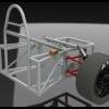
Joe, the car looks great as always. Those stands are an awesome idea!
#170
Joe250
-
- Just Joined
-
- 215 posts
Mini Mad
- Location: California
Posted 16 November 2010 - 06:50 PM
Thank for the kind words, everyone.
My floors are particularly weak and mangled. I had to do something.
by the way, I got some inspiration from your build on how to deal with my lower dash problems. I should have some photos up in a week or two. Any updates on your thread?
Joe
Joe, the car looks great as always. Those stands are an awesome idea!
My floors are particularly weak and mangled. I had to do something.
by the way, I got some inspiration from your build on how to deal with my lower dash problems. I should have some photos up in a week or two. Any updates on your thread?
Joe
#171
tedmcedd
-

- Traders
-
- 2,751 posts
Up Into Fourth
- Location: Huddersfield
Posted 20 November 2010 - 06:51 PM
those stands are fantastic!! hmmm.... may have to put a full cage in now so i can do it! hahaa!
Ed
Ed
#172
charie t
-

- Members
-
- 3,153 posts
Up Into Fourth
- Location: South Leicestershire sticks
- Local Club: wreake mini wanderers
Posted 20 November 2010 - 09:26 PM
You appear to only have inner sills, no outer fitted

 Looking good though on the rest of it
Edited by charie t, 20 November 2010 - 11:01 PM.
#173
Joe250
-
- Just Joined
-
- 215 posts
Mini Mad
- Location: California
Posted 21 November 2010 - 06:35 AM
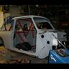
You appear to only have inner sills, no outer fitted
You are correct. This is yet another strange thing the previous owner did to this car. You'll notice the custom steel flares and connector piece. Sadly, the latter is somewhat fragile in its current state. I'll be working with the bodyshop to install the outer sills and reinforce the flare connectors at the same time. Wish me luck!
Edited by Joe250, 31 October 2012 - 01:59 AM.
#174
mini-geek
-

- Members
-
- 1,169 posts
One Carb Or Two?
- Location: Ormskirk
Posted 21 November 2010 - 10:17 AM
looks to me that it is an early floor pan where the outer sill is part of the floor and the inner is a separate piece,
#175
Joe250
-
- Just Joined
-
- 215 posts
Mini Mad
- Location: California
Posted 20 December 2010 - 07:46 AM
Some more progress, this time on the lower dash. This is one area I've been dreading. The upper and lower dashboards were cut out of the car prior to me purchasing it. As I've said before, I wanted to keep the car looking as close to original wherever possible. For the interior that meant keeping the centrally-mounted instrument panel and keeping the original dashboards. Most of the upper dash was long gone but I was able to easily replace it with a new part. The Mk1-style lower dash is not available new, so I had to work with the original one and a Mk4-style dash from Heritage.
Of course there were complications. The custom pedal assembly I had installed passed right through the plane of the lower dash. Further, the location of the roll cage's front 'legs' meant I could not insert or remove the lower dash without first removing the entire pedal assembly. I had put off solving the lower dash problem until now but it was holding things up. I decided to re-think things and suddenly realized that I really didn't want/need the lower dash to be removeable in the first place. A friend had recommended going that route and once I accepted the idea I didn't question it again until now. Now I just didn't see the point.

When I first tried mounting the lower dash in the stock position, I had to butcher the heck out of the front (see above). This basically ruined the panel - it lost all strength at that end and was a couple bends away from snapping like a paperclip. It also didn't look right to have the dash located behind the cage. I decided to move the dash outwards to make the front of it flush with the roll cage legs. It would have to move outwards (towards the back of the car) about 2-3", which most people would not be able to detect. It would ease the installation method as you'll see in a moment. And most importantly it allowed the dash to almost completely clear the master cylinders .

One problem with moving the dash backwards in the car is that sides of the car there are diverging. Basically I was moving a slice of pizza away from the rest of the pie. I would need to widen the dash by a few inches to fit into its new location. Luckily I had two dashboards - the original and one new one. I would use the center section of the original dash and the sides of the new dash.

The next step was welding in a length of steel tubing where I wanted to mount the dash. I curved it to match the countours of the dash, notched the ends, and welded it in place.

I would mount the face panel of the dash directly to this crossbeam, then fabricate a custom dash panel to form the floor of the dash.

The first problem with this idea was that the tube was too large in diameter to allow the switch panel to be mounted to the center of the dash.

Fixed!

I cut out the offending section of tube, essentially splitting the tube lengthwise along that section. I then welded on a flat strip of steel and ground it all smooth. The end result is a round tube that has a 'D' profile section.

I then welded in a length of square tubing along the firewall followed by two support tubes running to the dash tube. This would give enough strength to allow me to hang the heater underneath the center of the dash and the ECU tray from under the righthand side.

I welded the center section into place.

Then I trimmed the righthand side of the new dash to length and test-fit it.

I welded the two together as well as welding the dash face to the cross tube.


The dash face needed very minimal trimming to clear the master cylinders.

I went back and smoothed out the welds. When it is painted it should look pretty good.

One other thing I decided to change while I was at it was to ditch the machined aluminum steering column support and fabricate one from steel. I decided to use two more of the steel bolt-on supports. Part of the reason for this change is that I didn't fully trust the aluminum support - and why should I? I made it! The other reason is that I was very unhappy with how sloppy the remote brake/clutch fluid reservoir setup had become. I don't like the idea of filling the reservoirs inside the car when it is all painted and the interior trim is all in place but it is the lesser of two evils. I'll just have to be extra careful.

Here you can see the dash in place as well as the master cylinder reservoirs. You'll also notice that three sections of the dash floor with a section left out entirely for the pedal assembly.

And here is the steering column as it sits now. I fabricated a new horizontal support using thick-wall steel tubing. It just barely squeezes inbetween the two brake fluid reservoirs.

Of course there were complications. The custom pedal assembly I had installed passed right through the plane of the lower dash. Further, the location of the roll cage's front 'legs' meant I could not insert or remove the lower dash without first removing the entire pedal assembly. I had put off solving the lower dash problem until now but it was holding things up. I decided to re-think things and suddenly realized that I really didn't want/need the lower dash to be removeable in the first place. A friend had recommended going that route and once I accepted the idea I didn't question it again until now. Now I just didn't see the point.
When I first tried mounting the lower dash in the stock position, I had to butcher the heck out of the front (see above). This basically ruined the panel - it lost all strength at that end and was a couple bends away from snapping like a paperclip. It also didn't look right to have the dash located behind the cage. I decided to move the dash outwards to make the front of it flush with the roll cage legs. It would have to move outwards (towards the back of the car) about 2-3", which most people would not be able to detect. It would ease the installation method as you'll see in a moment. And most importantly it allowed the dash to almost completely clear the master cylinders .
One problem with moving the dash backwards in the car is that sides of the car there are diverging. Basically I was moving a slice of pizza away from the rest of the pie. I would need to widen the dash by a few inches to fit into its new location. Luckily I had two dashboards - the original and one new one. I would use the center section of the original dash and the sides of the new dash.
The next step was welding in a length of steel tubing where I wanted to mount the dash. I curved it to match the countours of the dash, notched the ends, and welded it in place.
I would mount the face panel of the dash directly to this crossbeam, then fabricate a custom dash panel to form the floor of the dash.
The first problem with this idea was that the tube was too large in diameter to allow the switch panel to be mounted to the center of the dash.
Fixed!
I cut out the offending section of tube, essentially splitting the tube lengthwise along that section. I then welded on a flat strip of steel and ground it all smooth. The end result is a round tube that has a 'D' profile section.
I then welded in a length of square tubing along the firewall followed by two support tubes running to the dash tube. This would give enough strength to allow me to hang the heater underneath the center of the dash and the ECU tray from under the righthand side.
I welded the center section into place.
Then I trimmed the righthand side of the new dash to length and test-fit it.
I welded the two together as well as welding the dash face to the cross tube.
The dash face needed very minimal trimming to clear the master cylinders.
I went back and smoothed out the welds. When it is painted it should look pretty good.
One other thing I decided to change while I was at it was to ditch the machined aluminum steering column support and fabricate one from steel. I decided to use two more of the steel bolt-on supports. Part of the reason for this change is that I didn't fully trust the aluminum support - and why should I? I made it! The other reason is that I was very unhappy with how sloppy the remote brake/clutch fluid reservoir setup had become. I don't like the idea of filling the reservoirs inside the car when it is all painted and the interior trim is all in place but it is the lesser of two evils. I'll just have to be extra careful.
Here you can see the dash in place as well as the master cylinder reservoirs. You'll also notice that three sections of the dash floor with a section left out entirely for the pedal assembly.
And here is the steering column as it sits now. I fabricated a new horizontal support using thick-wall steel tubing. It just barely squeezes inbetween the two brake fluid reservoirs.
Edited by Joe250, 20 December 2010 - 07:48 AM.
#176
Joe250
-
- Just Joined
-
- 215 posts
Mini Mad
- Location: California
Posted 20 December 2010 - 07:47 AM

Now on to the ECU tray. With all the various electrical systems in the car I needed a bit more space to neatly mount them near the firewall. I decided that mounting them underneath the dash would be about the best spot. Here I am laying out various control units on a template of the tray. The upper left box is the R1 ECU. The bottom one is the Pro-Shift controller. The Power Commander piggyback ECU is to the right and the Speedohealer is at the top. Like everything on this car, it is going to be a tight sqeeze.

By creating a hinged tray I can create a little bit more space, keep everything out of sight, but still make everything easily accessed. I welded a steel tube to the firewall and mounted a length of piano hinge to it.

I then installed two Dzus quick-release latches.

Finally, I installed a catch strap to hold the tray whenever the ECU's are being accessed.
#177
charie t
-
- Members
-
- 3,153 posts
Up Into Fourth
- Location: South Leicestershire sticks
- Local Club: wreake mini wanderers
Posted 20 December 2010 - 11:31 AM
Now i do like that Joe, very tidy idea!
#178
Stevee
-

- Members
- 0 posts
- Local Club: #
Posted 20 December 2010 - 12:13 PM
Looking good joe 
can't wait to see it finished
can't wait to see it finished
#179
Chris C
-
- Members
-
- 212 posts
Mini Mad
Posted 20 December 2010 - 10:28 PM
I checked your site yesterday hoping for an update, and then I accidentally stumble across your thread on here today.
I really like your dash solution, I know exactly what you're talking about in terms of space conflict with the Tilton setup, except you fixed it correctly and I went about hacking things up. What do you plan on doing to cover the reservoirs? I won't hold it against you if you decide to keep them on display, like god intended.
I didn't realize how small the R1 ECU is, the Honda one is absolutely massive in comparison. I guess that applies to the whole conversion, thought.
Joe, I'm going to be heading up to San Francisco in a month or two, If I fly into SFO what's the best way to get down to your area? I'd love to check the car out in person and steal more ideas.
#180
Joe250
-
- Just Joined
-
- 215 posts
Mini Mad
- Location: California
Posted 21 December 2010 - 12:40 AM
I checked your site yesterday hoping for an update, and then I accidentally stumble across your thread on here today.
I really like your dash solution, I know exactly what you're talking about in terms of space conflict with the Tilton setup, except you fixed it correctly and I went about hacking things up. What do you plan on doing to cover the reservoirs? I won't hold it against you if you decide to keep them on display, like god intended.
I didn't realize how small the R1 ECU is, the Honda one is absolutely massive in comparison. I guess that applies to the whole conversion, thought.
Joe, I'm going to be heading up to San Francisco in a month or two, If I fly into SFO what's the best way to get down to your area? I'd love to check the car out in person and steal more ideas.
Agreed - the Tilton pedals are great. Fitting them into this car is not. I could make some cover for the reservoirs, probably in fiberglass. I hadn't given it much thought but I will probably leave them exposed.
The R1 ECU is pretty small. I just wish that was the only thing I had to mount. It will probably end up a mess of wires in the end, despite all my planning.
Email me and we'll set something up. I'll be in LA for the holidays. Care to give me a tour first?! I'LL be doing the idea stealing around here!
Joe


1 user(s) are reading this topic
0 members, 1 guests, 0 anonymous users


