So today is the second anniversary of purchasing the Mini. This is taking far longer than I ever would have guessed. Some of the delays are due to scope creep. Some are due to me having to do everything twice - once the wrong way and again the wrong way but differently. It's far too late to go back so all I can do is push forward.

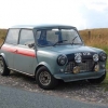
Here is what she looked like the night I took delivery.

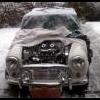
And here was one year ago.

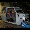
And this photo was taken today. She looks worse than a year ago but looks can be deceiving. The engine started up a few weeks back and the car should be driveable in a few weeks. Only the electrical system and interior/exterior trim remains (more or less).

Although the engine fired up earlier this month, I skipped a few details about what it took to make that happen so let me re-cap. First of all, it took a lot of time - about 35+ hours a week for 10 weeks straight. That was fun. Two days before my deadline I was ready to re-install the engine, fill the various systems with fluids, and hook up the wiring harness. I held off though since I had an empty engine bay and it would be a good opportunity to fill and test the front brake system. This turned out to be yet another example of me learning things the hard way. No sooner had I filled the system with brake fluid and bled the system than I found leaks at nearly every junction in the system. This would take some serious work to repair so I tightened most of the fittings a bit more, drained the fluid back out, and moved forward with re-installing the engine. More on re-doing the entire brake system later.

Putting the engine back in took just a few hours and with all the plumbing in place it was finally time to fill all the various systems with fluids. I started with the fuel system. Because the process of cutting the fuel lines to length and installing fittings creates metal and rubber dust, I decided it would be a good idea to flush the lines with fuel prior to hooking them up to the fuel pump and fuel rail. This was made extremely easy with my trusty MotionPro auxiliary fuel tank and a spare AN fitting.

I routed the fuel lines in the boot through a drain hole in the floor and into a bucket. I also remove the fuel tank then sloshed some fresh fuel around inside before dumping it out.

Then it was time to fill up the cooling system. Because I would be draining the system again soon I decided to just use straight water for now. Like the fuel system, I decided to flush the system a bit before filling the system completely. Immediately I ran into a problem with water filling the pockets in the valve cover. I feared the worst for a moment but I shouldn't have. The o-rings were left off of the coolant outlet tubes. Placing a new set on the tubes immediately fixed that problem. With the lower drain plug open, I placed the garden hose into the radiator inlet and ran copious amounts of water through the system.
After that I filled the transfer box system with oil followed by the motor itself. Thankfully I purchased some relatively inexpensive motorcycle-specific engine oil. This meant I wasted only $30 instead of $50 or $60 when all of that oil drained onto the garage floor. I had leaks everywhere. Fixing all of them took me well into the week after start-up. More on that shortly. Back to prepping the engine for start-up...

I am glad I took the time a few weeks prior to mark every electrical connection on the engine and wiring harness as well as familiarizing myself with the layout of the harness. This made temporarily installing the harness a very quick and easy process. I think it took all of 20 minutes for the bulk of the work with another hour or so of jumpering miscellaneous items and diaganosing a few minor problems. It doesn't look pretty having the harness draped over the dash and engine bay but it would do the trick.

The day of the engine start-up was when work on the oil leaks began. One of them was easy to fix. My friend Will quickly guessed that I had installed the sandwich plate upside down on the remote oil filter housing and a quick check revealed he was right. That was easy to fix. The sending units plugged into the sandwich plate also leaked due to their thread type. Rather than using teflon tape I decided to try Loctite 545, a liquid equivelant. I've only run the engine briefly since installing it but so far it is holding.

The final leak proved frustrating to fix. Oil was dripping out of the oil filter take-off as well as the fittings screwed into the take-off plate. It took a lot of trial and error to figure out that the plate was bottoming on the R1's filter bolt before the plate's rubber o-ring was forming a tight seal against the block. I machined the plate's nut some more and this finally did the trick. The plate made almost 1 additional revolution than before tightening up against the block, so no surprise that it was leaking oil before. Finally, I switched to another style of fitting for the hose connectors that tighten into the plate and was able to tighten them down enough to stop the leaks. Finally!!!

Now it was time to fix the brakes. I started by pulling the engine yet again. And leaking more oil everywhere.

With the motor out I was able to do a few quick items like re-do the hydraulic clutch line, wire up the reversing motor, and adjust the engine idle - something we noticed when the engine got up to temperature.

For the initial brake line install over a year ago I had purchased a complete Mini brake line kit from the UK along with an inexpensive flaring tool and tube bender. This, combined with my total ignorance of all aspects of brake line plumbing and some mismatched parts meant that brake problems were inevitable. Last week I took a few days and started educating myself on the various types of flares, the best material for rigid brake lines, and the right tools for the job. I decided upon using AN 37-degree single flare fittings and 3/16 Bundy weld steel tubing for the hard lines partly because they seemed the best fit for my car and what I plan to do with it but also due to the fact that Carroll Smith recommends it in his book. Good enough for me.

This Ridgid brake flaring tool came highly recommended and I can see why. It is well-built, easy to operate, and makes perfect flares. I still think cunifer is an excellent choice for brake lines but I'm going to take the advice I received and stick with steel throughout. For a normal street car cunifer is fine.


I removed the old cunifer lines and used their shape as a template for bending the new lines. I also took this opportunity to relocate the brake light switch, install bulkhead fittings (something I definitely should have done before), and also install quick-release fittings. These last items will allow me to drop the front subframe without leaking brake fluid everywhere and without having to re-bleed the brake system upon reassembly.


http://www.joe250.com/cars/mini/rebuild/step47/IMG_3815.JPG" It is hard to tell from this photo but I installed all the tubing so that the lines are always headed upwards or at least level when moving from the wheels towards the master cylinders. This should help prevent air pockets forming in the lines and make bleeding a bit easier.
[img]
http://www.joe250.co...47/IMG_3821.JPG I ended up re-locating the rear brake proportioning valve and routing the hardlines differently than what this photo shows. I've almost got the rear brake lines finished. Sometime this week I should be able to fill and bleed the system and try it out. If all goes well, that will be one of the last items needed before the car is ready for its first test drive.


