Jump to content


Photo
- - - - -

Old Rover Rev-counter


  • Please log in to reply
13 replies to this topic

#1 JamesF

JamesF

    Mini Mad

  • TMF+ Member
  • PipPipPipPip
  • 228 posts

Posted 16 June 2008 - 09:05 PM

I have a rev counter from an old Rover 214 or 414. I've taken the dial out of the instrument panel. Normally it would work from a printed circuit on the back of the panel but the actual dial has three connections.

The two green squared screws are only mounting screws. But the three red squared screws are the electrical connections. The red and black wires at the back are from a multimeter.


Posted Image


Posted Image


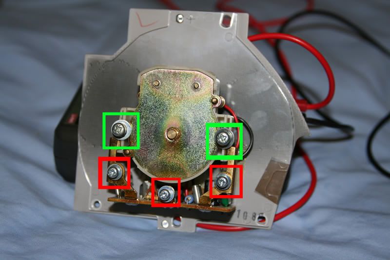
Presumably it could work the same as any other rev counter using these three points. I was going to try it with a 1990 carburettor 998cc. Is there a way I can test it without putting a billion amps through it from the engine? Does anyone have the remotest idea how to wire it up? i.e. what each connection on the dial is likely to be for. Is it even possible to use a tachometer from an ECU controlled engine in a carburettor engine? =]

#2 day101

day101

    Super Mini Mad

  • Members
  • PipPipPipPipPipPip
  • 610 posts
  • Local Club: Dont have one:(

Posted 16 June 2008 - 09:36 PM

the wires go on the coil, if you got a haynes manual i think there is information in there

Edited by day101, 16 June 2008 - 09:36 PM.


#3 captain kirk

captain kirk

    One Carb Or Two?

  • TMF+ Member
  • PipPipPipPipPipPipPip
  • 857 posts

Posted 16 June 2008 - 09:51 PM

one wire to earth,one to live,one to coil

Edited by captain kirk, 16 June 2008 - 09:51 PM.


#4 JamesF

JamesF

    Mini Mad

  • TMF+ Member
  • PipPipPipPip
  • 228 posts

Posted 16 June 2008 - 09:57 PM

the wires go on the coil, if you got a haynes manual i think there is information in there


Haynes doesn't go into much detail about individual clocks. I've got one for a Rover 214 and the Mini and pretty much all it says is how to take the entire instrument panel out.

one wire to earth,one to live,one to coil


So in a Mini, earth (I think the middle one) would connect to some metal body work.
Left or right connects to the black/white bullet connector.
The other side goes to the green spade connector.

That's clicked now and seems fairly obvious. What happens if it's connected back to front?

#5 captain kirk

captain kirk

    One Carb Or Two?

  • TMF+ Member
  • PipPipPipPipPipPipPip
  • 857 posts

Posted 16 June 2008 - 10:10 PM

thats a good question i have no idea

#6 JamesF

JamesF

    Mini Mad

  • TMF+ Member
  • PipPipPipPip
  • 228 posts

Posted 16 June 2008 - 11:16 PM

I had a brainwave. :thumbsup:

Earth is used for all components. Positive must be a standard signal. But the signal coming from the coil mustn't interfere with anything else. So surely that would be connected on its own. I had a look at the printed circuit on the back of the instrument panel, and the track going from the left pin wasn't connected to anything else, it just went straight to a point where the multiplug should go.

I'll try it that way tomorrow and see if I set the car on fire.

#7 pantera2075

pantera2075

    Super Mini Mad

  • Members
  • PipPipPipPipPipPip
  • 596 posts
  • Local Club: GTMOC

Posted 17 June 2008 - 07:41 AM

You might find you develop a misfire if you do this - there's nothing to say the resistance in the new tacho is anything like the mini fitment ones. I tried this years ago with an Alfasud tacho and it stole spark energy and made for very yucky running.

#8 JamesF

JamesF

    Mini Mad

  • TMF+ Member
  • PipPipPipPip
  • 228 posts

Posted 17 June 2008 - 07:49 AM

You might find you develop a misfire if you do this - there's nothing to say the resistance in the new tacho is anything like the mini fitment ones. I tried this years ago with an Alfasud tacho and it stole spark energy and made for very yucky running.


Interesting point. Would it make anything blow up or would it just be a bit rough?


And before I do anything, are these wires under the dash the ones I want? Dark green with a spade connection for positive and White/black with a bullet connection for the coil.


Posted Image

#9 Retro_10s

Retro_10s

    Moderator

  • Members
  • PipPipPipPipPipPipPipPipPipPipPip
  • 10,138 posts
  • Location: Bromsgrove

Posted 17 June 2008 - 08:17 AM

i can confirm the white and black one is the coil feed. not sure about the green one. test it to see if it's live.

#10 pantera2075

pantera2075

    Super Mini Mad

  • Members
  • PipPipPipPipPipPip
  • 596 posts
  • Local Club: GTMOC

Posted 17 June 2008 - 08:30 AM

Might cook your coil, melt the points/condensor or more likely just blow the tacho.

Green is usually ignition switched fused live.

#11 JamesF

JamesF

    Mini Mad

  • TMF+ Member
  • PipPipPipPip
  • 228 posts

Posted 17 June 2008 - 05:08 PM

I had a good look under the dashboard for a Green/orange wire but the only ones I can see are both connected to a voltage regulator cylinder thing.


In this thread, not so mini shows the cylinder with a dark green wire on one side and a green/orange wire on the other. Further down they show a loose green/orange wire which they used for the rev counter.

Which way should it be?


I could get a picture of mine but you just need to imagine this picture having two green/orange wires connected to the cylinder.

#12 HARBER07

HARBER07

    Up Into Fourth

  • Traders
  • PipPipPipPipPipPipPipPipPip
  • 4,498 posts
  • Location: Suffolk
  • Local Club: Naaa......

Posted 17 June 2008 - 05:28 PM

That "cylinder" is the flasher unit for the indicators. So would be a switched live (i think).

Edited by HARBER07, 17 June 2008 - 05:29 PM.


#13 JamesF

JamesF

    Mini Mad

  • TMF+ Member
  • PipPipPipPip
  • 228 posts

Posted 17 June 2008 - 08:13 PM

:xxx: Good news:

I managed to get the tachometer working and it seems to give an accurate reading.


:unsure: Bad news:

It involves running a wire from the coil, outside the car and in through the window.


I had decided to check the wires under the bonnet after trying to understand Haynes' wiring diagrams. There was a cable on the coil negative going to the distributor but no other wires there. So I have the connector inside the cabin to go there but no wire actually connected to it. As a quick fix [Don't try this at home unless accompanied by mature, adult supervision!], I thought I would run a wire from the coil negative straight to the tachometer. From the picture in the first post, I linked the middle screw to earth, the right screw to the loose green spade connector and the left screw to the coil negative.

I did a quick start and vroom of the engine. After it settled down it was idle at 1,500rpm (sounded a bit loud) and a little pressure on the pedal took it up to 3,000rpm.


Can anyone tell me where the black/white wire should come out in the engine bay?

#14 captain kirk

captain kirk

    One Carb Or Two?

  • TMF+ Member
  • PipPipPipPipPipPipPip
  • 857 posts

Posted 17 June 2008 - 08:16 PM

well done glad it works :unsure:


1 user(s) are reading this topic

0 members, 1 guests, 0 anonymous users