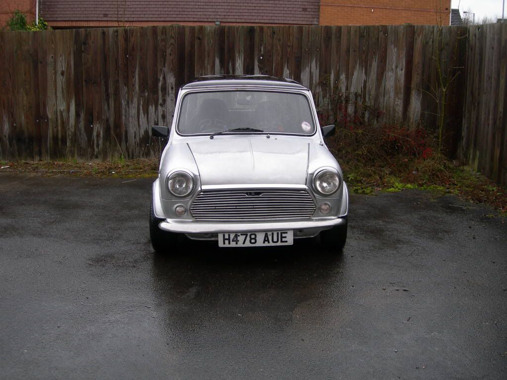
Suzuki Swift Gti Engined Mini
#1
Posted 13 January 2008 - 05:49 PM
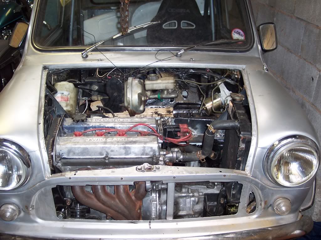
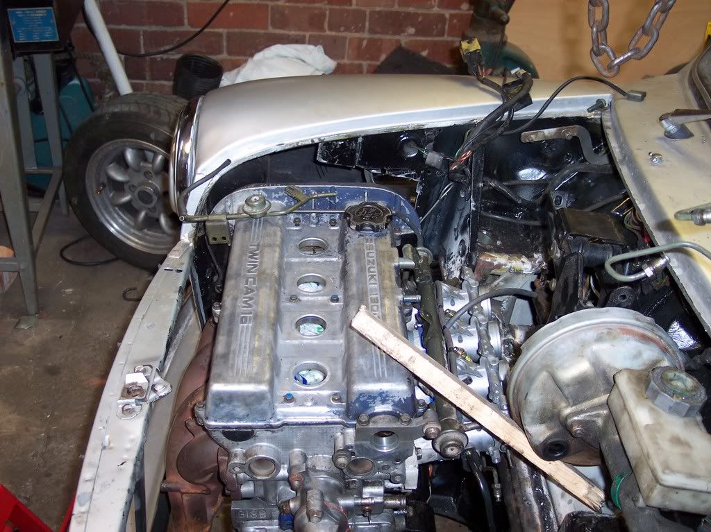
Engine spec
swift gti engine
suzuki gsxr 1000 quad throttle bodies with itg air filter
custom inlet manifold (cast at home)
megasuirt ecu
edis 4 ignition system
wide band lamda sensor
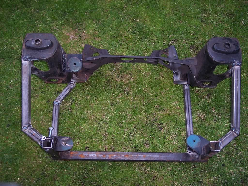
custom subframe
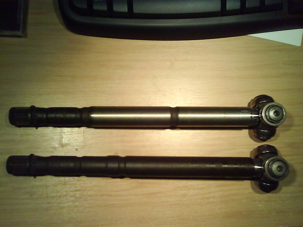
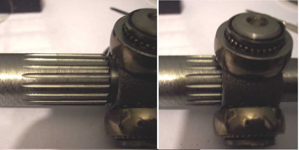
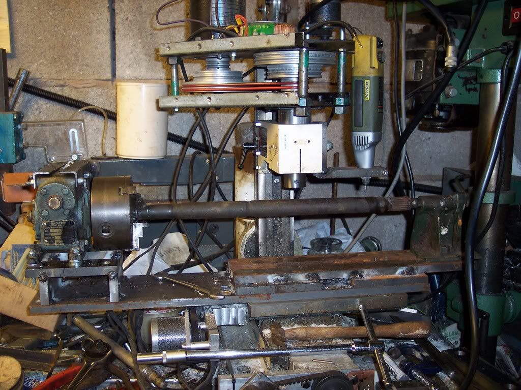
splines cut on mini driveshafts with CNC machine
custom exhaust
mpi tank
2 core mini rad
standard brake servo
car spec
wheels 12x5 but may upgrade to 13x6
cobra bucket seats
red harness's
fibreglass dash
suzuki instruments
#2
Posted 13 January 2008 - 06:59 PM
#3
Posted 13 January 2008 - 07:11 PM
#4
Posted 13 January 2008 - 07:41 PM
by the way Ed..have got any pics or diagrams of James's fuel system setup? trying to sort out where to put the idle control solenoid on the throttle bodies!
#5
Posted 14 January 2008 - 07:32 PM
Rhys
#6
Posted 15 January 2008 - 10:21 PM
p.s If anyone needs driveshafts...we are able to cut suzuki splines on mini driveshafts with the aid of a cnc machine and might even be able top do vauxhall or vtec buit not untill project is on the road.
Edited by iamcabaged, 15 January 2008 - 10:22 PM.
#7
Posted 16 January 2008 - 06:52 PM
fuel from pump goes to the large pipe on rail, medium is return and small needs to go to the ITBs after the butterflies, (where it will get vacuum)
For the idle solenoid one air pipe goes before the throttle bodies, but after the filter so its clean air, the other goes after the butterfly on all the ITBs so each gets more idle air.
Can draw pics if you need any more info
#8
Posted 16 January 2008 - 09:00 PM
p.s If anyone needs driveshafts...we are able to cut suzuki splines on mini driveshafts with the aid of a cnc machine and might even be able top do vauxhall or vtec buit not untill project is on the road.
nice project, just a little question though, dont the drive shafts need to to be diffrent lenghs to the minis ones? and the drive shafts would have to be shortened to suit each application if they are useing a custom frame. however...
however, all ive seen is where they are in this car. however this one sits a little lower down but from the wing lip there isent much diffrence.
nice project, might be an idea for a swift engine if i cant stomac the cost of the 970 engine i plan to build.
#9
Posted 16 January 2008 - 10:57 PM
flyinggears2002 - we put the engine in the position where the driveshafts are the same length, the Suzuki engine has an intermediate support bearing on the tight hand driveshaft with a CV joint....so it all worked out fine. we cut them from standard mini driveshafts and there is plenty of metal to cut them long and short if needed. We can put the splines on at the required length and all that needs doing then is putting the slots in for the circlips and cutting them down to the right length.
cheers
#10
Posted 16 January 2008 - 11:00 PM
home made cnc machine
#11
Posted 16 January 2008 - 11:50 PM
#12
Posted 17 January 2008 - 01:46 AM
No pics sorry, but it is simple enough,
fuel from pump goes to the large pipe on rail, medium is return and small needs to go to the ITBs after the butterflies, (where it will get vacuum)
For the idle solenoid one air pipe goes before the throttle bodies, but after the filter so its clean air, the other goes after the butterfly on all the ITBs so each gets more idle air.
Can draw pics if you need any more info
Ed,
That sounds fine, I'm not sure yet where to connect the idle, If I put it into the old Yamaha injector positions, I can make a manifold up for it. That leaves the original 4 vacuum connections on the TBs for the Megasquirt connection. I can then cut a thread in the manifold for the Servo connection. I'm a bit concerned that with the brake servo coming off no 1 and the Megasquirt coming off all 4 that the servo vacuum will affect the megasquirt... does it need non-return valves in there somewhere ? Or doesn't
The alternative would be to take the Servo off No 1 and the Megasquirt off No4 only, with non-return valves in the idle connection. Its all a bit of a puzzle
FYI
I looked at the setup for the injectors in more detail, the resistance of the standard Suzuki injectors puts them right at the limit of what the megasquirt will run, I think we will put some resistors in series with the injectors, I have some 6.8 Ohm 10 watt, so doubling up that will give 3.2 Ohms 20 Watt or 2.3 Ohms 30 Watt with three for each injector.. If it runs OK with them in, it will help reduce the load on the output of the megasquirt.
We are leaving the double crankshft pulley on and welding the trigger wheel to the outside of that so that maybe (once the car has been driven for a while and if it's safe) we can use it to drive a supercharger, the ones fitted to the BMW Mini seem to be about the right size, and look as though they will fit above the current inlet manifold. We would have to drop the compression ratio, if we can't find the right pistons, we could CNC a spacer plate with two head gaskets.
Has anyone built a Minuki with a supercharger ?
so much to do and so little time... but making progress... Trigger wheel sensor on tomorrow )
Chris (iamcabbaged's Dad)
Edited by spiyda, 17 January 2008 - 01:15 PM.
#13
Posted 22 January 2008 - 06:03 PM
you should only need one non-return valve in the pipe to the servo, and having a large pipe between all inlets will help balance them (of not completely).
If you already have a V3 its not hard to add the flyback circuit, but the resistors should work to. I think the difference is PWM adds more control and better response for the injectors.
I know what you mean with the Bini charger, so much so that one came in the post last week
Ed
#14
Posted 22 January 2008 - 06:23 PM
#15
Posted 22 January 2008 - 06:59 PM
Im saving for a hobby mill then eventually ill convert it to CNC.
but then i also want a new welder so im just saving the pennies now.
1 user(s) are reading this topic
0 members, 1 guests, 0 anonymous users