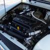
Bought early '96 Spi cooper. Drove home no problems, all seems ok but temperature gauge only just climbs to top of blue (only JUST) and no oil light working. Faults checked as follows...
Pull off oil pressure sender wire and touch on engine with ignition on.... light on dash lights.... diagnosis faulty sender...replacement about £2:70....fault cleared.
The Coolant Temperature Sensor, (CTS). This is a bit more difficult. The CTS is a negative temperature coefficient thermistor. On the Spi its range of resistance vs temperature is as follows
Temperature Resistance
0 deg C 6K
20 deg C 2400-2600R
40 deg C 1100-1300R
60 deg C 500ish Ohms
80 deg C 300ish Ohms
100 deg C 100ish Ohms
These values dont take into account the wiring in the loom and the corrossion on your connectors...lol
First change is the thermostat. 88DegC is specified for a late Spi Cooper they arent expencive and this could save you a lot of time, money and effort. If changing this sorts the Gauge or your other problems then you can buy me a pint with the money you have saved not having to do the rest of this.
As the coolant heats up to the 88 degC the resistance of the CTS starts to drop. This drop is read by the ECU and the injector timing is varied accordingly, its not a binary on off switch, it varies the injector timing against the ECU map. An NTC Thermistor is highly unlikly to fail in the short circuit mode, (ie almost never ever will this be the situation), but will more than likley fail either open circuit or its resistance over time will start to creep up . ie at say 80 degC instead of reporting 200 ohms it might be more like 600-1000 ohms. This tells the ECU that the injector timing needs to be extended. Maybe not full timing but certainly not where it should be.
Someone on this forum asked can the sensor be shorted to the body to test it. The answer should be... no dont try this.... The CTS is independant of the body earth... its a 2 wire system..... one side, Pink/Green, goes direct to the ECU terminal 33, the other side is pink/Black this goes to ECU terminal 30 and can also be found in the 3 pin fault diagnosis connector. Its possible that the other sensors in parrallel with the CTS are the intake air temperature sensor and the throttle potentiometer, ( I say possible cause Im only refering to the wiring dia I have and although they show terminations going into the ECU at diff terms I dont know what the input buffers are like inside).... both of these are resitive in nature and due to ohms law will change relative to each other if one or more of them vary...... obviously in a fully heated engine the sensors reach a stable resistance value but it does mean that if one fails, (and remember 2 of these sensors are likly not to completly fail but just change resistance curves) then all sorts of problems can happen..... specifically Missfires.... high idle speed low idle speed....irregular idle speed.... poor fule consumption..... temperature gauge that wont read mid gauge...poor emmissions (usually reading high but could be only just over)..... seeming loss of power.
The CTS is one of the primary sensors in the ECU map.....if it goes wrong OR MUCH MORE LIKLEY just starts to report the wrong value then all sorts of problems can show up that you might not think are related to it.
So.....how to test.... first of all..... is your temp gauge reading correctly... it should be somewhere very near mid gauge line... if not check you have an 88 degC thermostat THAT WORKS... or just change it anyway they are about £4 and sooooooooo easy to do this job. The best way to check the sensor would be to attach a digital meter across the sensors 2 wires, (loom disconnected) and monitor the resistive state of the sensor as the engine warms up, it should change from say a relativly high reading of 6-10 K Ohms on a cold engine to about 200 Ohms on a working temperature engine. This WOULD be the way to do it but as we all know that sensor is in a really bad location ie no access at all.
So the only access is to get to the ECU terminal. This is an AMP econoseal 36 way terminal on the late SPI Coopers. Its a well tried and tested automotive connector, and as such is almost bullit proof in respect of keeping water and gook out of the ECU. This means is very difficult to push a Digital meters probes into the silicon wire seals and get to the terminals. Also the wiring loom is short and I dont like cutting wires. Before starting this MAKE SURE THE ENGINE IS AT WORKING TEMPERATURE or you might fool the ECU into thinking their are other faults, at the very least it will be difficult to start. I got a couple of 100 ohm resistors 1/4 watt and with the ECU connector disconnected very carefully slid the thin resistor wires into the Pink/Green terminal 33 seal and the other resistor into the Pink/black terminal 30 seal down the sides of the wires. They have to go a fair way in. twist the 2 other ends together and you have 200 ohms( with 2x100 ohm resistors in series). plug the connector back in.... start the engine and check the temperature gauge..... if the CTS has been reporting high putting these resistor in parrallel with it effectivly lowers the resistance, the temp gauge should go up FROM WHERE IT WAS PREVIOUSLY but shouldnt get as far as the red section. The engine should idle at 800 rpm. If the faults you had are cleared you can now almost 100% say the sensor is faulty and strip manifolds and change the CTS. If the temp guage reads almost to the red or into it then chances are it isnt the CTS..... but from here id suspect the air inlet temperature sensor which is a lot easier to change and is a lot cheaper to buy. Remember to remove your test resistors.
Keep in mind that if you have been running the engine effectivly rich then chances are the Lambda sensor is now kippered as the sensor will have been soaked in rich gasses for too long, and so as you have all this stripped then change it any way.
While im here...... Sprocket mentions the 4 wire lambda sensor from here http://www.cats-dire...bda-sensors.php Can you confirm this is the one to use and what you mean by splcing the sensor into the plug..... is the heater wires Black and Blue/red to the 2 white wires? Does the Black signal on the sensor go to 13 or 14 on the ECU, and the Grey earth to the other one?). Also where is the cheapest place to get a replacement CTS?
OK..... why have I written this.... Ive read so much on this forum and information is hard to come by. The manuals are difficult to read sometimes and sketchy on the information about wiring and the sensors. Some of the pepole here have got faults that fit into the above scenario but might not think that the CTS has anything to do with their problems. I have seen somone with a high reading guage...... this is possibly the reverse of my problem... ie a CTS with low resistance.... but remember these sensors hardly ever fail short.... this is far more likley to be CTS wiring shorting out.... especially as this sensor is so close to hot exhaust pipes. This test wont diagnose this fault but testing the resistance or the CTS from the ECU plug with a cold engine should give a reading of in excess of 6K ohms ECU plug disconnected and close to 200 Ohms with a hot engine and plug disconnected. You cant read the sensor resistance in real time unless you have a test book computor cause the ECU needs to be connected for the engine to run. So this is the best method I've found to sort it. The ECU takes information from sensors that if they fail will stop the engine....... but it also takes info from sensors that can output the wrong information and just change the way the ECU 'thinks' the engine is performing and so alters its outputs accordingly. The CTS is one of those.
Thanks for listening........ hope this helps anyone who had my problems.
Standard disclamer applies..... tin hat at the ready ...lol...
Edited by DaveRob, 21 October 2007 - 08:56 AM.


