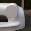
Custom Minis R1 Clubman Estate
#61

Posted 26 May 2008 - 06:38 PM
Plenty of strength built in!!
Cheers
#62

Posted 01 June 2008 - 07:20 AM
Cool, Love the doorbars mate!!!
Plenty of strength built in!!
Cheers
Cheers Mark, they're not finished yet either, another bar to come!
#63

Posted 01 June 2008 - 07:49 AM
Even on its limit, the front end ground clearance was still 5" off the floor.
(ignore the tyres, I'm not running them like that, just so I can get the thing on 4 wheels)
Basically, the idea is to reduce the turret heights which will higher the front subframe within the car thus levelling out the top arms but at the same time lowering the car.
To do this I used some simple sized box section, I tack welded a 50x25 to the centre webbing and a 50x25 over the turret mounts. I'd hoped for 3" but as it worked out I had 60mm between the underside of the top 50x25 box and the spacer 50x50 box.
Numerous cutting and grinding discs later...........
and then a little bit of welding..........
You can see the big gaps that are present because of the reduced height, the turrets actually taper top to bottom. As said its just a trial at the moment, I'll try the subframe now as it is and see what ride height can be achieved. If it all works out I'll look to have new top plates made - laser cut to suit the shape of the turret.
fingers crossed......
Les.
Edited by Custom_Minis_Ltd, 01 June 2008 - 07:53 AM.
#64

Posted 01 June 2008 - 09:12 PM
(above) tried to get the same picture position as yesterday with standard subframe in situ.
At this position I have 3" ground clearance but are not totally happy with the incline the top arms have, people keep telling me that lowered A series Minis with a standard subframe has the same angle - anyone got any pictures??
Also, the steering rack, although not shown will definately need the drop link system that the miglia's run.
I'm still going to keep at it though, I settled on 3.5" ground clearance the top arms were still inclined more than I'd like but we'll see.
I also offered the front end up to the car and found that the front spolier has 4.5" ground clearance and I definately don't want that going up so its gotta stay at this.
Edited by Custom_Minis_Ltd, 01 June 2008 - 09:13 PM.
#65

Posted 01 June 2008 - 10:25 PM
Cheers
David
#66

Posted 01 June 2008 - 10:32 PM
The top arms are normally angled up, take a look at any kit car, obviously you don't want any extreme angles, but considering how low it is the angle is not bad
Cheers
David
Hi David,
Thanks for the re-assurance!
Just got bump steer to worry about now
Cheers,
Les.
#67

Posted 02 June 2008 - 12:05 AM
#68

Posted 04 June 2008 - 06:08 PM
I wish I could even find somebody that has carbon panels for my MK3.
#69

Posted 04 June 2008 - 07:21 PM
Les looking amazing!!!!!!!!!!!
I wish I could even find somebody that has carbon panels for my MK3.
Thanks!
If you look a couple of pages back, theres a post from Rogue Sevens, the guys name is Jim. I had some Carbon headlights rings from him - they're top notch items, really recommend his stuff and his your side of the pond too!
Maybe he can help you??
Cheers,
Les.
#70

Posted 06 June 2008 - 06:29 PM
Things are looking great. As for your suspension issues, I've done a lot of research into suspension angles and there are some nice online programs that will help you determine caster, camber, and bump steer for a given geometry, I can try to find them again if you are interested. Also it is good to keep in mind that the ball joint on the Mini is in the knuckle, so even though the angle of the arms relates to the suspension geometry, the actual or maybe I should say theoretic line is from the pivot of the arm to the center of the ball joint, which make the line of the suspension closer to level than it would appear.
#71

Posted 29 June 2008 - 07:31 PM
The picture below shows the bodyshell running with 3" ground clearance:
As you can see the steering rack incline is horrendous.
This is how it looks in the bay in its orginal position:
........and this how I'm going to try and modify the position. Cut away the original mounting bracket, drill a new clearance hole for the rack lug/column mount and introduce a cross bar into the subframe and mount the rack to it.
Hopefully, this will reduce the angle of the steering rack and then any incline left will be taken up by the Miglia style drop links.
Any feedback greatly appreciated..........
(except about the poor rack bracket picture that there 4yr old could of done better)
Cheers,
Les.
Edited by Custom_Minis_Ltd, 29 June 2008 - 07:51 PM.
#72

Posted 30 June 2008 - 08:10 PM
#73

Posted 30 June 2008 - 09:55 PM
Sorry about my relatively limited knowledge of steering and suspension, but by steering incline, do you mean the angle from the steering rack centre, relative to other suspension components or something?
Your limited knowledge? probably more than me!
I'm refering to the end of the rack, where the rod end sits. The incline after the knuckle joint. I know its got something to do with bump steer - the travel of the rack pulling the hub in different directions as it moves through its own axis etc....
Basically.......help!
Just require one of the more techinical Z Cars builders to confirm I'm not wasting my time, I'd prefer to get this sorted rather than spend a £1000.00 on the subframe, which I think will have inclined rack arms as I'm running such low ground clearance. However, if I can't get this right...at least I've tried and then I'll have to buy the subframe.
Les.
#74

Posted 30 June 2008 - 10:37 PM
SportPro Series - The Sports Car & -Kit Car Suspension and Brakes High Performance Manual - very good book for the basics!
Basically, Looking from the front, draw an imaginary line from the top arm pivot (subframe end), do to the bottom arm pivot (again, subframe end). You want the inner ball joint of the steering rack to lie on this line, or as close to as possible.
Secondly. Looking either from the front or the side, measure the distance from the ground to the track rod ball joint (steering arm end). The inner ball joint on the rack should be exactly the same height up (+/- 1.5mm).
If I'm reading my book right, you get those two conditions right and you should pretty much eliminate bump steer! Of course you have the two obvious conditions that the rack MUST be parrellel both to the line between the two hubs, and also parrellel to the ground.
#75

Posted 01 July 2008 - 02:07 AM
1 user(s) are reading this topic
0 members, 1 guests, 0 anonymous users


