Do keep us advised of your progress. Let us know your final cost on the custom FX4 transducer and how it works with your speedo. Thanks for your updates so far.


Electrical speedo
Started by
ckneller321
, Jul 22 2007 02:27 PM
57 replies to this topic
#31

dklawson
-

- TMF+ Member
-

- 10,923 posts
Moved Into The Garage
- Name: Doug
- Location: Durham, NC - USA
- Local Club: none
Posted 29 December 2008 - 01:51 PM
#32
phil hill
-

- TMF+ Member
-
- 616 posts
Super Mini Mad
- Location: Lincoln, UK
Posted 30 December 2008 - 01:58 PM
Hi Doug
Well when I spoke to Matthew at Salis he said he'd make the transducer with the square drive for the same price as the standard FX4 transducer, so that's £24 before post and tax. All in delivered to my door it was £34.
It looks a lot like the examples posted earlier in the thread, but with a deep section nut attached rather than the spigot for the cable to clip onto.
My only concern is whether there is enough clearance behind the gearbox for the transducer to fit without fouling on the subframe or bulkhead. If the temperature increases here over the remainder of the holidays (it's about freezing point here at the mo) then I'll have a go at fitting it to the car.
Thanks for the support and interest from earlier in the thread and from the original post.
Phil.
#33
phil hill
-
- TMF+ Member
-
- 616 posts
Super Mini Mad
- Location: Lincoln, UK
Posted 01 January 2009 - 02:52 PM
OK, I've taken some pics of the sensor and it fitted to my spare gearbox for reference if anyone is interested.
 sensor1.JPG 68.99K
14 downloads
sensor1.JPG 68.99K
14 downloads
sensor2.JPG 59.69K
14 downloads
sensor3.JPG 77.44K
14 downloads
sensor4.JPG 74.93K
15 downloads
Phil.
sensor1.JPG 68.99K
14 downloads
sensor2.JPG 59.69K
14 downloads
sensor3.JPG 77.44K
14 downloads
sensor4.JPG 74.93K
15 downloadsPhil.
#34
ckneller321
-
- Members
-
- 224 posts
Mini Mad
- Location: Northampton
Posted 01 January 2009 - 10:56 PM
See what you mean about the clearance. I haven't got round to fitting mine either, still need to get a few bits so I can complete my dash all in one go.
Mine's slightly different to yours. I have a cable for between the gearbox and transducer so will have the transducer elsewhere and won't have the clearance issue.
Mine's slightly different to yours. I have a cable for between the gearbox and transducer so will have the transducer elsewhere and won't have the clearance issue.
#35
phil hill
-
- TMF+ Member
-
- 616 posts
Super Mini Mad
- Location: Lincoln, UK
Posted 03 January 2009 - 09:16 PM
See what you mean about the clearance. I haven't got round to fitting mine either, still need to get a few bits so I can complete my dash all in one go.
Mine's slightly different to yours. I have a cable for between the gearbox and transducer so will have the transducer elsewhere and won't have the clearance issue.
Well I had a look on another car which was on the ramp at my local Mini place today and I don't think the size will be a problem.
Any chance you could take a picture of your sensor for comparison ?? This was the one from speedy cables yes ??
Thanks
Phil.
#36
ckneller321
-
- Members
-
- 224 posts
Mini Mad
- Location: Northampton
Posted 04 January 2009 - 07:04 PM
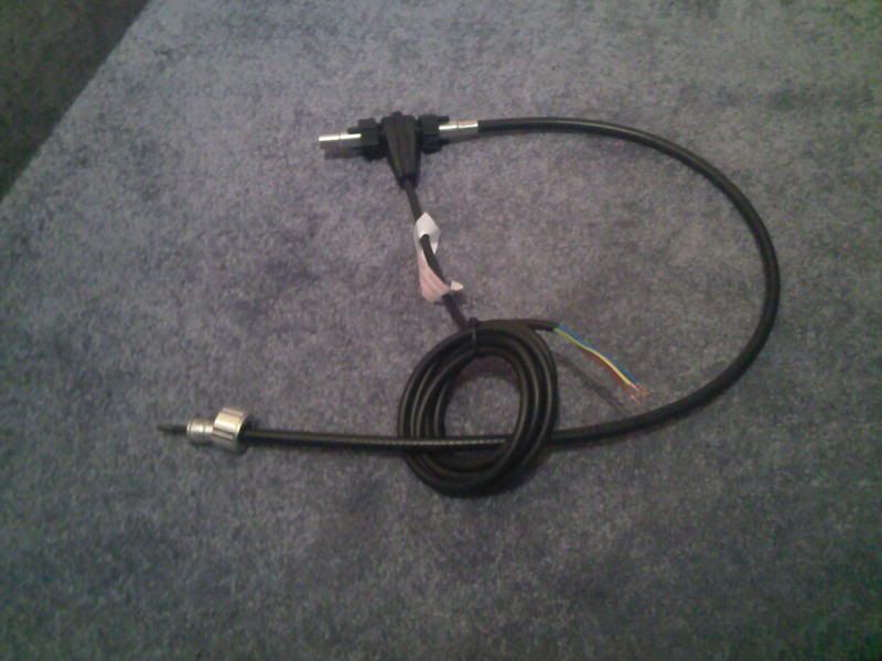
That's the one yeah.
Here you go.
Here you go.
#37
phil hill
-
- TMF+ Member
-
- 616 posts
Super Mini Mad
- Location: Lincoln, UK
Posted 05 January 2009 - 01:24 PM
That's the one yeah.
Here you go.
Well looking at that I can absolutely confirm that speed sensor is made by Sailes !! The lable on the cable and the fact that the cable is 3 core mains type flex is identical to mine.
I didn't realise you were connecting it to a speedo cable, that was exactly what I didn't want to do !! Looks good though, are you going to mount it in the engine bay or run it inside the car ??
It still hasn't been warm enough for me to go and lie outside on my drive to install the sensor or calibrate it (must be getting old as I've worked outside in Canada at -30 deg C before.........) and now I'm back to work. Hopefully I'll be able to report complete success very soon !!
Phil.
#38
ckneller321
-
- Members
-
- 224 posts
Mini Mad
- Location: Northampton
Posted 05 January 2009 - 07:42 PM
Not sure where to put it yet. Was intending inside to try and protect it a little but may just go the direct route following where the existing cable goes. Then it will be in the engine bay I expect because the cables less than a meter long.
Still undecided.
Still undecided.
#39
Danuneek
-

- Members
-
- 452 posts
Speeding Along Now
Posted 06 January 2009 - 12:36 AM
Lastly, the binnacle in the back of the picture is a used unit I picked up off eBay just to have. The speedometer in it is a hybrid. It's a Smiths housing but I've transplanted a VDO speedometer with custom face behind the glass. You'll notice the odometer window is an LCD screen. My intention is to install that gauge in my next Mini project.
Wow, thats exactly what I need, i've even got a spares smiths speedo. How hard was it to build and have you got anymore pics of it as I fancy building one myself. What model VDO did you use to fit it so perfectly. Are they relatively easy to set to the correct speed do you know?
Edited by Danuneek, 06 January 2009 - 01:42 AM.
#40
dklawson
-
- TMF+ Member
-
- 10,923 posts
Moved Into The Garage
- Name: Doug
- Location: Durham, NC - USA
- Local Club: none
Posted 06 January 2009 - 03:31 AM
VDO's common aftermarket electronic speedometers all have a part numbering scheme of 437-### where the "###" spells out the gauge series and size. Internally they are identical with only programming differences. Almost any 120 MPH speedo in this family will be suitable. Or... occasionally you'll find an 85 MPH model that may be suitable. (I have bought several off of eBay... I actually bought another one over Christmas. $20 (delivered) used with about 2700 miles on the odometer.)
My conversion represents a tremendous amount of work for a DIY project. I only took on this challenge as it was something I thought about years ago when I first got our Triumph. I have built three such speedometers, one for the Mini, one for the Triumph, and one for a Jeep. Each was different, each required machining parts, each required making a new face for the gauge.
Suffice it to say that you have to open up the VDO gauge and carefully remove the LCD from the back of the gauge face and you have to remove the stepper motor driving the needle from the circuit board on which it mounts. You must machine an acrylic carrier for the LCD, you must make components to mount the VDO board on the BACK of the Mini gauge case and you must make a new decal (or screen print) for the gauge face. You also have to make an extension for the LCD's ribbon cable and make an extension harness to mount the needle's stepper motor to the back of the gauge face. Again, it's not an easy project. I spent a lot of time designing each installation before machining the first part.
As for how accurate they are, very. The VDO speedometers are programmable using one of three different modes. You can put the car on a rolling road (or drive using a GPS showing the speed) and adjust the needle on the fly. Or, you can do math and calculate the number of pulses per mile from your sending unit and directly enter that value. Lastly, you can drive a measured distance and let the speedometer calculate and enter the pulses per mile. The programming is very easy. The rolling road/GPS and/or measured distance programming modes are the most accurate as they take into account the exact diameter of your tires at the time of programming.
Edited by dklawson, 06 January 2009 - 03:34 AM.
#41
Danuneek
-
- Members
-
- 452 posts
Speeding Along Now
Posted 06 January 2009 - 12:40 PM
Does anyone know if an electric speedo exists in the style or near to the style of the classic Smiths mini speedo? The thing is I need a new speedo but I want to keep the possibility of changing from 13" to 10" wheels open in the near future and therefore want something I can calibrate easy. The electric speedo sounds perfect but I love the classic style.
Edited by Danuneek, 06 January 2009 - 12:40 PM.
#42
dklawson
-
- TMF+ Member
-
- 10,923 posts
Moved Into The Garage
- Name: Doug
- Location: Durham, NC - USA
- Local Club: none
Posted 06 January 2009 - 12:58 PM
To the best of my knowledge there are no aftermarket electronic speedometers as large in diameter as the classic Mini center speedo. There's also the issue of the fuel gauge and all the indicator lights to deal with.
I'm sorry if my gauge conversion gave your false hope. If you've got your own machine tools (lathe and mill as a minimum) and a real passion to try this I could send you PDF versions of some of the CAD drawings I made for the parts I machined.
I'm sorry if my gauge conversion gave your false hope. If you've got your own machine tools (lathe and mill as a minimum) and a real passion to try this I could send you PDF versions of some of the CAD drawings I made for the parts I machined.
#43
phil hill
-
- TMF+ Member
-
- 616 posts
Super Mini Mad
- Location: Lincoln, UK
Posted 12 January 2009 - 09:39 AM
OK, so I wrapped up warm yesterday and had a go at fitting the sensor. It's just not pleasant working outside this time of year, especially when you've been used to the luxury of a mate's warm workshop with a lift !!
Anyway, the sensor fits the gearbox when mounted in the car !! I'm going to change the 7/16 bolt which attaches the speedo drive to the gearcase for the shouldered 3/8 one on my spare gearbox as the sensor fixing nut just fouls on the bolt head at the very bottom of it's thread before going tight.
I fashioned a little pointer for the speedo drive and counted the turns of the speedo drive wrt turns of the road wheel before I fitted the sensor, so I have an idea of the relationship between the two for calibration purposes.
I put in some random figures to the speedo and drove through the gears to see that speedo read speed (with the car securely stood on axle stands and the wheels off...... Safety first guys !!), which it did after taking a little while to get the motor fired up !! Also managed to pop the gaiter off the pot joint and cover everything in CV joint grease, which was nice......... and a little bit of grease spat out of the nsf wheel bearing as well, but on the whole it seems that this is a successful option for those wanting to generate a pulse signal for an aftermarket speedo. I'll call Mathew at Salis and let him know.
I took some pics, but I left the camera at home, so I'll post them another day.
Phil.
#44
dklawson
-
- TMF+ Member
-
- 10,923 posts
Moved Into The Garage
- Name: Doug
- Location: Durham, NC - USA
- Local Club: none
Posted 12 January 2009 - 01:48 PM
Excellent news !!! Thanks for keeping us up to date.
Since you have an open dialogue with Sailes maybe you could suggest that they make this version of the sending unit with the 3/4-26 threads a standard product for them. It would NOT be unique to the Mini. It could be used on a lot of Triumph and MG models from the 1960s through the mid to late 1970s. I'm sure they could sell it in the U.S.
As for the bolt on the gearbox, I assume you mean the 7/16" (across flats) hex head bolt on the speedo output flange. If clearance is a problem you could probably change to a 1/4 UNC Allen Head bolt. This type...
http://www.5speedtra...enHeadBolt.jpeg
It will be harder to get in/out but it will certainly offer clearance around the adapter.
Refresh my memory. What did you end up paying for the custom sender?
#45
phil hill
-
- TMF+ Member
-
- 616 posts
Super Mini Mad
- Location: Lincoln, UK
Posted 13 January 2009 - 11:13 AM
If you're telling me that MG's and Triumph's have the same size connection for the speedo cable then providing there is sufficient clearance for the sensor between gearbox and chassis or bodywork then there is no reason why this won't fit.
You are absolutely correct about the bolt I was refering to, an Allen head bolt would do it's just that I have a smaller flanged screw on my other gearbox so when I can get the car up in the air next I'll change them over.
I think there may have been a problem with my counting of turns though as my observations don't corespond with any permutation of diff ratio and speedo drive gear, so I'm going to have to revisit that...........
Anyway pics as promised :
sensor6_800.JPG 235.88K
19 downloads
View looking through NSF wheel well - the car doen't have inner wings.......
sensor3_800.JPG 221.88K
17 downloads
Closer view, you can just make out the bolt and metal plate which retains the speedo drive.
sensor5_800.JPG 179.04K
13 downloads
View from underneath, big rusty looking bar is the drive shaft, and you can see the CV grease all over the bottom of the sensor !!
Bearing in mind where the thing is, and that it's very difficult to get any meaningful pictures that's about the best I could do.
Price including delivery (recorded) and VAT was £34 and change.
Phil.
You are absolutely correct about the bolt I was refering to, an Allen head bolt would do it's just that I have a smaller flanged screw on my other gearbox so when I can get the car up in the air next I'll change them over.
I think there may have been a problem with my counting of turns though as my observations don't corespond with any permutation of diff ratio and speedo drive gear, so I'm going to have to revisit that...........
Anyway pics as promised :
sensor6_800.JPG 235.88K
19 downloadsView looking through NSF wheel well - the car doen't have inner wings.......
sensor3_800.JPG 221.88K
17 downloadsCloser view, you can just make out the bolt and metal plate which retains the speedo drive.
sensor5_800.JPG 179.04K
13 downloadsView from underneath, big rusty looking bar is the drive shaft, and you can see the CV grease all over the bottom of the sensor !!
Bearing in mind where the thing is, and that it's very difficult to get any meaningful pictures that's about the best I could do.
Price including delivery (recorded) and VAT was £34 and change.
Phil.


1 user(s) are reading this topic
0 members, 1 guests, 0 anonymous users


