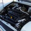
Inertia switch
and then you need a schematic

Best Answer seria , 26 April 2007 - 04:25 AM
Would it possible to post some pictures together with the explanation? I can take picture and send it to you if needed. So far i don't quiet follow as it involve so many relays.
Thanks.
Go to the full post 
Posted 25 April 2021 - 08:50 AM
Inertia switch
and then you need a schematic
Posted 03 March 2022 - 08:10 PM
Hello,
On the relay pack - small connector - I am trying to figure out the use for the pink/black (pin 5 I think)
reading through this thread it sounds like it is just a ground wire for the intake heater relay.
Other than that does it have a purpose?
If it make a difference I have an older 2 plug SPI ECU
This pink/black wire goes from the small connector on the relay pack to pin 6 on the large connector on the ECU
Posted 04 March 2022 - 07:00 AM
You are right, but in connection with ecu`s, the black or "ground wires" are the steering or control lines.Power or plus is always there, ground is switched by the ecu!
Posted 05 March 2024 - 10:39 AM
If the ECU is not grounding the fuel pump relay coil, first check the crankshaft sensor.
Does the fuel pump run for a second or two when the ignition is turned to position II (IGN)? If yes then the ECU is OK, and it's likely a crankshaft sensor problem.
One other thing to check, does the main relay also pull in when ignition is turned to Position II (IGN)?
Stepper motor will motor the throttle full closed and back open again when ignition key off. If it doesn't there is a more fundamental problem than just the fuel pump relay.
Hi there I am having a similar problem to the one being discussed, my question is what is the more fundamental problem as my main relay does not pull in when ignition is turned on, it will pull in however if i connect an earth
look forward to any response
Posted 05 March 2024 - 04:43 PM
main relay has 4 subrelais, which one isn´t working?
Posted 05 March 2024 - 05:56 PM
Yes, sorry for any confusion, but I was referencing the piece that sprocket wrote on the spi relay pack and how it works.
Posted 08 March 2024 - 03:48 PM
Just a quick update if anyone can help, I checked the main brown wire on the relay pack and it gives me 12v with the red lead connected to it and the black lead connected to a common ground, but if I connect the the black lead to the black/purple wire coming from the ecu and crank the engine it only gives 1-2 volts, which will not allow the main relay to energise. Any suggestions or is the ecu at fault or just a dodgy earth
Posted 08 March 2024 - 04:51 PM
Referring to post 1 in this thread
Logic explained
When the key switch is turned to IGN 12v is supplied to the ECU on a white wire this powers the ECU. The ECU will then initiate the fuel pump for 10 seconds and then de activates it again if there is no further activity. Turn the key to CRK the starter is initiated (if the imobiliser/alarm is off, where fitted). Activity is recorded by the ECU on the Crank Position Sensor. The ECU then initiates the Main relay. This provides power to the ignition coil, stepper motor, purge valve solenoid, and ECU directly on the brown pink, and the injector via the ECU. The engine should now start. Once the RPM is above a predetermined RPM the manifold heater is initiated until the coolant temp measures 75c or more it is then de activated. The Main relay, and fuel pump relay, are the only ones to be energised when the engine is running and fully warmed up.
first check if the other things work.Then check if the mainrelay gets ground from the ecu. Speak cranc position sensor.
Posted 08 March 2024 - 05:46 PM
The main relay is not getting its ground from the ecu, so if I push the contact in manually ( on the main relay) everything works as it should and the engine runs fine, but it won’t stay energised, with me holding in the contact manually it allowed me to connect my Sykes pickivant code reader and it was showing no errors.
Posted 09 March 2024 - 03:42 PM
Have the ecu checked.
Posted 09 March 2024 - 08:25 PM
0 members, 1 guests, 0 anonymous users