Jump to content


Photo
- - - - -

Innocenti Upgrade - Part 1 - Fuel Injection


  • Please log in to reply
116 replies to this topic

#106 Bill USN-1

Bill USN-1

    Mini Mad

  • Members
  • PipPipPipPip
  • 260 posts

Posted 18 March 2007 - 08:12 PM

For the IAC there are basically 2 pairs.
The pink/blue and orange/slate.
and
Orange/blue and orange/green

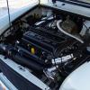
If you look at the pic you will see I have 2 sets of leads blue hi and low and green high and low.

Now since the motor drives to a neutral difference i don't think the swapping of the pairs matter as much as the hi and low.

I have the highs on the pink/blue and the orange/green wires. That's stepper phase 2 and 3.

Hope it helps but mine is a GM system so the names are a little different.
That's why you see the spade connectors...so I could swap them till it worked.

Posted Image


Now to your...where are you monting your knock sensor?
I didn't install mine just because I couldn't decide on a good spot to put it.
Normally they go in the block leading to the water jacket. Like a block drain hole.

When are you going to run the manifold heater? I didn't even hook mine up. Just the coolant for now. Seems to be working fine but I may run 12V to it as a test to see if it makes any difference in the AFR while running.

#107 nev_payne

nev_payne

    Up Into Fourth

  • Members
  • PipPipPipPipPipPipPipPipPip
  • 2,249 posts
  • Location: UK

Posted 18 March 2007 - 09:42 PM

mate those videos are great! proof of concept! =] being a little perfectionist like here - bit tappety? might just be the mic on the camera picking it up tho. Deffinately has a beautifully smooth take down from high speed and idle tho...really nice.

Very impressive work man :P

#108 Bill USN-1

Bill USN-1

    Mini Mad

  • Members
  • PipPipPipPip
  • 260 posts

Posted 18 March 2007 - 09:50 PM

It's still running on the original build valve adjustment.
I haven't reset them yet so they may be starting to tick.

Thanks!!

#109 nev_payne

nev_payne

    Up Into Fourth

  • Members
  • PipPipPipPipPipPipPipPipPip
  • 2,249 posts
  • Location: UK

Posted 18 March 2007 - 10:10 PM

ahhh- that'd be why then heh. =]

#110 Sprocket

Sprocket

    Great on Injection faults

  • Members
  • PipPipPipPipPipPipPipPipPipPip
  • 7,266 posts
  • Location: Warrington
  • Local Club: Manchester Minis

Posted 18 March 2007 - 10:10 PM

For the knock sensor. i'll just be using the lower bolt for the alternator bracket on the A+ block, But you have 7 !! extra bolt locations on the mpi block to fiddle around with, two right on the deck next to a combustion chamber, Ideal if you ask me. Thats where im fitting them on the 16v, I have the option of two knock chanels and i think i'll use them, one either end of the block. Thing is though, i have the ability to tune the sensors frequencey to the block and there location.

As for the stepper, yeh, i think i'll have to do what you have and swap them around to get the polarity right. When you say 'hi, lo' does this mean +ve and -ve respectively?? obviously there needs to be +ve and a -ve for the motor to work, but then the ECU will reverse the polarity to change motor rotation. and if both windings are oposing each other, the motor wont move, likewise they could be doing the oposite that the ECU wants.

#111 Bill USN-1

Bill USN-1

    Mini Mad

  • Members
  • PipPipPipPip
  • 260 posts

Posted 18 March 2007 - 10:20 PM

If you look at the pick you will see each of my pair have a white stripe and a black stripe wire.
just like + and -
The blue pair is IAC "A" and the green pair is IAC"B"
Black is lo and white is hi

I may end up playing with the knock sensor now that it's all working.
I really have come to lean on it when tuning the timing curve.
Makes it convenient to see when it starts to ping before you really hear it!!!
And I can run some retard for the really hot thin air days!!

#112 Sprocket

Sprocket

    Great on Injection faults

  • Members
  • PipPipPipPipPipPipPipPipPipPip
  • 7,266 posts
  • Location: Warrington
  • Local Club: Manchester Minis

Posted 18 March 2007 - 10:28 PM

If you look at the pick you will see each of my pair have a white stripe and a black stripe wire.
just like + and -
The blue pair is IAC "A" and the green pair is IAC"B"
Black is lo and white is hi


Thanks mate, that gives me an educated place to start =]

Oh yeh the manifold heater, this only functions on cold start, if you are using the water heating, then its use is purely limited to cold start. It is a PTC heater so as the temp rises so does the resistance resulting in less current draw and therefore less heat. The MEMS ECU controls it on coolant temp switching it off above a certain engine temp.

Edited by Mini Sprocket, 18 March 2007 - 10:32 PM.


#113 fikus01

fikus01

    Camshaft & Stage Two Head

  • Members
  • PipPipPipPipPipPipPipPip
  • 1,910 posts
  • Local Club: SMAG - Southend Mini Action Group

Posted 19 March 2007 - 12:55 AM

well done bill, she sounds cool, its amazing that sum1 got the whole lot going at last, she does sound a little lean when u rev it from tickover, guess u wont know til u start to play with the wideband o2! keep it coming tho,

#114 Bill USN-1

Bill USN-1

    Mini Mad

  • Members
  • PipPipPipPip
  • 260 posts

Posted 19 March 2007 - 06:44 AM

well done bill, she sounds cool, its amazing that sum1 got the whole lot going at last, she does sound a little lean when u rev it
from tickover, guess u wont know til u start to play with the wideband o2! keep it coming tho,


I think what you are thinking as lean is the stepper motor that extends when you open the throttle. The amount it extends is based on temp tables and the amount the throttle is opened.
What this does on the SPI is the stepper motor actully pushes the throttle open and then there is a stepper decay table to tell it how fast to return to idle. This is not a carb where the slide hangs open although the results are about the same.
If you noticed the idle drops back down on it's own as the stepper motor retracts.
The AFR when warm is right on 14.7 but I will check cold start and what AFR when the WBO2 is hooked up.


As for the ticking....I started it back up and listened but heard no lifters ticking. I think what might be heard on the video is the injector firing. It sounds almost the same.

Edited by Bill USN-1, 19 March 2007 - 06:44 AM.


#115 Sprocket

Sprocket

    Great on Injection faults

  • Members
  • PipPipPipPipPipPipPipPipPipPip
  • 7,266 posts
  • Location: Warrington
  • Local Club: Manchester Minis

Posted 19 March 2007 - 05:52 PM

The injector is noisy from around 2500 rpm =]

Most often mistaken for tappets, same way as is the mech fuel pumps

#116 Boomboy77

Boomboy77

    Mini Mad

  • Members
  • PipPipPipPip
  • 285 posts
  • Local Club: WSMOC

Posted 11 April 2007 - 08:19 PM

Hey Bill, looking good mate. Im just about to do the same but using a MS, now what I would realy like is how you set you software to drive the IAC please :thumbsup:

#117 Bill USN-1

Bill USN-1

    Mini Mad

  • Members
  • PipPipPipPip
  • 260 posts

Posted 13 April 2007 - 07:31 AM

Hey Bill, looking good mate. Im just about to do the same but using a MS, now what I would realy like is how you set you software to drive the IAC please :withstupid:


I'm running mine with the GM ECM. I have been tweaking the GM IAC setting since the original resistance values of the IAC were different.
I would have to look at the MS software to see if the IAC tables compare to the GM tables.

But I found the Rover idle controller needs about 1/2 the counts as the GM IAC.

At the stock park position of 145 counts I can idle the 1275 to about 2500-3000 rpm. She drives to 12.5% throttle position.


1 user(s) are reading this topic

0 members, 1 guests, 0 anonymous users