


Innocenti Upgrade - Part 1 - Fuel Injection
Started by
Bill USN-1
, Jan 02 2007 10:56 PM
116 replies to this topic
#31

Bungle
-

- Members
-

- 28,971 posts
Original Spamster
- Location: Cornwall
- Local Club: cornish mini club
Posted 12 January 2007 - 10:49 PM
what are you looking at apart from a cylinder head ?
#32
Bill USN-1
-
- Members
-
- 260 posts
Mini Mad
Posted 13 January 2007 - 09:14 AM
what are you looking at apart from a cylinder head ?
I asked Sprox about an unleaded 940 since mine does not appear to have the hardened seats.
So he posted the pix of his up here.

#33
Bill USN-1
-
- Members
-
- 260 posts
Mini Mad
Posted 15 January 2007 - 08:17 PM
OK I spent the weekend doing all those time consuming little things like making brackets, stripping parts, sanding and painting, trying to work out the plumbing......etc.
I finished up the front VR pickup bracket and got it all painted and installed. Cleaned up the pulleys and engine mount.

I was surprised how little it took to make the old V-belt alternator and pulleys work on the MPI block.
A simple L bracket and I had to drill and tap one of the mounting bosses on the block. All the other ones were drilled and tapped except the one I needed.

I also made a couple of brackets to mount the coil pack. Then cut and routed the plug wires.

Then I went to work on the plumbing.
I needed to plumb the FI manifold and the heater so I ended up just putting T's in the line. I thought the copper might look good as a contrast color but now that it's on I don't really like it.

Also made up a hard line from the timing cover vent up to the throttle body port.

So now I'm just about down to the wiring and firing her up. I'm really tempted to hook up the laptop and battery and fuel and just run it on the ground prior to dropping it in. But that would mean wiring twice and another intake gasket.

Still need to work out an aircleaner!!!
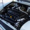
And what is the sensor just above the oil pressure relief?
Oil temp?
I finished up the front VR pickup bracket and got it all painted and installed. Cleaned up the pulleys and engine mount.
I was surprised how little it took to make the old V-belt alternator and pulleys work on the MPI block.
A simple L bracket and I had to drill and tap one of the mounting bosses on the block. All the other ones were drilled and tapped except the one I needed.
I also made a couple of brackets to mount the coil pack. Then cut and routed the plug wires.
Then I went to work on the plumbing.
I needed to plumb the FI manifold and the heater so I ended up just putting T's in the line. I thought the copper might look good as a contrast color but now that it's on I don't really like it.
Also made up a hard line from the timing cover vent up to the throttle body port.
So now I'm just about down to the wiring and firing her up. I'm really tempted to hook up the laptop and battery and fuel and just run it on the ground prior to dropping it in. But that would mean wiring twice and another intake gasket.
Still need to work out an aircleaner!!!
And what is the sensor just above the oil pressure relief?
Oil temp?
Edited by Bill USN-1, 15 January 2007 - 08:21 PM.
#34
Sprocket
-
- Members
-
- 7,266 posts
Great on Injection faults
- Location: Warrington
- Local Club: Manchester Minis
Posted 15 January 2007 - 08:36 PM
Looking good there buddy 
Yes the plug above the pressure relief is an oil temp sensor. it was only ever used with the gauge on the dash and not actualy anything to do with the ECU. I suspect that in the design stage of the MPi it was considered a requirement, after all, the Rover 820 T series and K6 series had oil temp feed back. Notebly the MPi ECU is a the same MEMS as the K6 ECU. Some where along the line they binned the idea and found another use for the sensor instead.
I will point out that it looks like the fan is on back to front. It should be written on the hub section the orientation of the fan, IE, Engine Side.
*Edit* Fan orientation is correct, the brightness of my screen is BRIGHT and fooled me
Yes the plug above the pressure relief is an oil temp sensor. it was only ever used with the gauge on the dash and not actualy anything to do with the ECU. I suspect that in the design stage of the MPi it was considered a requirement, after all, the Rover 820 T series and K6 series had oil temp feed back. Notebly the MPi ECU is a the same MEMS as the K6 ECU. Some where along the line they binned the idea and found another use for the sensor instead.
*Edit* Fan orientation is correct, the brightness of my screen is BRIGHT and fooled me
Edited by Mini Sprocket, 15 January 2007 - 08:38 PM.
#35
Bill USN-1
-
- Members
-
- 260 posts
Mini Mad
Posted 15 January 2007 - 09:00 PM
Thanks, I am thinking of using the oil temp sender for my ECM eng temp if the values are the same. It will be a little slower to warm up but should work fine.
The fan was the easy part. It said this side to motor!!!
Even i could get it right....unless it was printed on the wrong side from the factory!!
Another question before I weld in the O2 bung.
Is the Y pipe correct turning out or do they normally turn in towards the center?
The fan was the easy part. It said this side to motor!!!
Even i could get it right....unless it was printed on the wrong side from the factory!!
Another question before I weld in the O2 bung.
Is the Y pipe correct turning out or do they normally turn in towards the center?
Edited by Bill USN-1, 15 January 2007 - 09:02 PM.
#36
Sprocket
-
- Members
-
- 7,266 posts
Great on Injection faults
- Location: Warrington
- Local Club: Manchester Minis
Posted 15 January 2007 - 10:46 PM
Exhaust collector as it is in the picture
The Lambda boss is normaly welded to the collector of #1 and #4 cylinders just behind the engine. This is where it works best as the gasses are still hot. Though only measuring two cylinders, thats how its done and doesnt pose a problem unless you have a leaky manifold gasket.
As for using the oil temp for engine temp
I'd be tempted to use the original coolant sensor, either in the manifold, or in the head's original location.
#37
Bungle
-
- Members
-
- 28,971 posts
Original Spamster
- Location: Cornwall
- Local Club: cornish mini club
Posted 15 January 2007 - 11:39 PM
is that coil pack going to be ok right at the front of the engine
we have problems with damp in the dizzy caps over here being right at the front of the engine :'(
we have problems with damp in the dizzy caps over here being right at the front of the engine :'(
#38
Bill USN-1
-
- Members
-
- 260 posts
Mini Mad
Posted 16 January 2007 - 07:07 AM
is that coil pack going to be ok right at the front of the engine
we have problems with damp in the dizzy caps over here being right at the front of the engine :'(
Coil packs are all sealed units with weather pack connectors so they are not as prone to water intrusion like distributors.
The Lambda boss is normaly welded to the collector of #1 and #4 cylinders just behind the engine. This is where it works best as the gasses are still hot. Though only measuring two cylinders, thats how its done and doesnt pose a problem unless you have a leaky manifold gasket.
I'm going to use a heated O2 in the collector to sample the overall AFR. It only takes about 10 seconds to heat up. My only concern is the difference with the siamesed cyl running at different mixes but I can tune for that. maybe make the baseline AFR 14.5 or something.
My other option is to just go open loop at idle and run a standard 1 wire sensor. It will take longer to heat up to the 600mv but will also work fine while driving.
I will also run a second bung for the wideband O2 sensor for on road tuning! The only way to fly!
Edited by Bill USN-1, 16 January 2007 - 07:11 AM.
#39
The Matt
-

- Admin
-
- 17,232 posts
You don't escape that easily.....
- Name: Matt
- Location: Overton, North Wales
- Local Club: Welsh Border Minis
Posted 16 January 2007 - 08:37 AM
This is a fascinating thread, only just read through it, but it kept me hooked. Well done Bill, can't wait to see this finished 
Just in case you should ever need it, I have a spare Inno wiring loom that you could butcher!
Just in case you should ever need it, I have a spare Inno wiring loom that you could butcher!
#40
Bill USN-1
-
- Members
-
- 260 posts
Mini Mad
Posted 17 January 2007 - 11:11 PM
Thanks for the offer on the wires. I may take you up on it.
OK latest update...
IT RUNS
Hooked up the Battery and poured a little gas(petrol) down the throttle body.
Hit the starter and she didn't even hesitate!!
WOOHOO
Check it out!! Not sure if you need an account to see it?
http://smg.photobuck...nt=firstrun.flv
or
video
Keep in mind that this is with no computer hooked up and just running of the base timing of 0° running off the coil pack ignition.
Edited by Bill USN-1, 17 January 2007 - 11:15 PM.
#41
Sprocket
-
- Members
-
- 7,266 posts
Great on Injection faults
- Location: Warrington
- Local Club: Manchester Minis
Posted 18 January 2007 - 01:54 AM
Nice one!!!
Any sign of that package yet!!
Any sign of that package yet!!
#42
Bill USN-1
-
- Members
-
- 260 posts
Mini Mad
Posted 18 January 2007 - 05:36 AM
Nice one!!!
Any sign of that package yet!!
Nothing yet.
It seems things are really slowed up after the holidays.
#43
ed4ran
-

- TMF+ Member
-
- 2,849 posts
Cadwell Event organiser
- Location: Stoke On Trent
Posted 18 January 2007 - 11:53 AM
Sounds really beefy  I guess its not got an exhaust on?
I guess its not got an exhaust on?
#44
miniboo
-

- Members
-
- 9,327 posts
Lord of Original Thinking
Posted 18 January 2007 - 11:58 AM
awesome work Bill a true pioneer
#45
Bill USN-1
-
- Members
-
- 260 posts
Mini Mad
Posted 18 January 2007 - 12:25 PM
I just hope the post man delivers me some packages tomorrow. I really want to get this dropped in and wired up.
It's LCB only right now.
Just enough to test it.
Did a compression test before firing it up.
It was running 155 on all 4.
Will check again after break in.
I'm also in a debate with MiniMania concerning the cam they sent.
I ordered the SW5 for the injected motor and they sent me a SW5 with the fuel pump lobe on it.
So I had to make a plug for the side of the block because the pickup will not go all the way in.
Now my concern is, are the cam specs the same for both with the fuel pump lobe being the only difference?


1 user(s) are reading this topic
0 members, 1 guests, 0 anonymous users


