Jump to content


Photo
- - - - -

Innocenti Upgrade - Part 1 - Fuel Injection


  • Please log in to reply
116 replies to this topic

#1 Bill USN-1

Bill USN-1

    Mini Mad

  • Members
  • PipPipPipPip
  • 260 posts

Posted 02 January 2007 - 10:56 PM

There are many different parts of this conversion so I figure I better divide it up by systems.

For this Part 1 I will address the fuel and ignition system I am planning on using.

When I got this car it had been setting for almost 3 yrs.
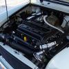
The engine steady and clutch end motor mount were broken which allowed the motor to beat the waxstat carb into the firewall. (note the rope tieng the engine steady!!!)
The transmission or transfercase gears sounded like C**p and it had bad vibrations. The more i fixed the more I found wrong.

This is what I started with..it actually cleaned up pretty good!! Typical small bubbles of rust starting in spots.

Posted Image

Posted Image

Posted Image

Posted Image

Well I did some research and found out the motor had already been swapped from a 998 to a 1098.

Since this is my first "mini" I was not sure how much of the noise was normal!!

So I started cleaning things up and getting everything working.
replaced all the motor mounts, pulled the carb and rebuilt it. Put all back together and fired it up. First drive was neat but the ride left a lot to be desired. So I started searching for places to get parts that the VAT and GB post cost would not double the price of!!!!
Minimania in the US carries a lot but if I have to pay those prices I won't be driving the mini much!! Did I mention I live in Italy right now?

But I did find Dave at www.GBcarsparts.com I think he carries a lot of minisports stuff and seems to be the cheapest. And he doesn't gouge shipping to FPO's(can only use USPS.)

I also met another Yank (starrider) living in London here on the board and he has really helped forwarding parts to me.

So that was my introduction to mini's. I got it running enough to drive...then I started to upgrade it.

First was the suspension. In went Hi-lo's and some new cones, monroe shocks, ball joints , tie rod ends, rebuilt the rack and pinion, rebuilt the alternator, bla...bla...bla...

The motor seemed to a little weak and like I said, she had some noises.
Well I picked up a 940 head and decided to give it a try.
Pocketed the block, installed the head, modified the 1098 rockers to work.
Fired it up and was fairly impressed with the new power.
Changed the oil and decided to install the magnetic drain plug. oops
Can't get it all the way in. Pull it back out and metal is stuck all over it......hmm

So I clean it all out and continue on.
Motor runs real good for about 1 week, then it starts smoking more and more.
Guess the rings didn't like the new compression ratio!!

Besides the noise in the tranny and vibration getting worse, I figured it was time to bite the bullet.

I had picked up a 97 MPI short block and tranny for free. Well you know how free goes...
So I decided this is my new powertrain for the mini....
Did I mention this was my first mini?????

Well I really started to learn how much they changed over the years!!

I will do a seperate Part 2 for the motor and head assembly!!

Edited by Bill USN-1, 02 January 2007 - 10:57 PM.


#2 Bungle

Bungle

    Original Spamster

  • Members
  • PipPipPipPipPipPipPipPipPipPipPip
  • 28,971 posts
  • Location: Cornwall
  • Local Club: cornish mini club

Posted 02 January 2007 - 11:25 PM

:w00t: keep us up to date

#3 Bill USN-1

Bill USN-1

    Mini Mad

  • Members
  • PipPipPipPip
  • 260 posts

Posted 02 January 2007 - 11:28 PM

Well Back on topic...

First I should say since I put my first fuel injection system on a motor I have never liked carbs since!!! :w00t:

So for my new power I decided I wanted Fuel injection.
Well as you may know there are 2 basic types, Throttle body injection-TBI, which is like an electronic carb or Multi port fuel injection-MPFI, which has 1 injector per cylinder and they are mounted in the manifold or head and shoot the fuel straight at the back of the valve. The manifold is just air. (no I will not discuss direct injection here).
The mini used their versions which were SPI and MPI.

Well I happened to pick up a MPI block. So what does that mean? Well for 1 there is no hole for a distributor!!! So now I also have to figure out how I am going to install ignition on this thing.

I started researching the systems and found that the design of the mini engine with it's simesed ports in the head does not work real well with the standard MPFI system. It would require some special software to be able to properly make it work.

But we all know the mini runs fine on a carb and the TBI system is nothing more then an electronic carb!!

So that is what I picked.

Now what parts do I want? I want a system that I can tune myself and will be able to grow with future mods.

Well mini already used the SPI system so if I get the intake and throttle body they may work for now.

So this is what I got.

Posted Image

I have several choices for the throttle body.
I can use the stock one if I can make it compatable with the computer I chose.
Or I can use a couple different GM TB's. One is a 1 barrel like the mini and the other a small 2 barrel.

Posted Image

Posted Image

Posted Image

Posted Image

Posted Image


Well I measured the resistance of the injectors and found the mini is the same as the GM's at 1.5 ohms.
The other parts of concern are the TPS-throttle position sensor...Well I found out the one on the mini TB is bad so I compared it with the GM unit....guess what...it's a bolt on match!!

Posted Image

So now all I have left is the idle control valve.

The GM uses an IAC-idle air controller that is a 4 pin stepper motor. The mini uses a 5 pin. well after talking to the FI guru here, and reasearching on the google.
We figured it would still work if the center contact was removed.

I measured the pins out and found that the resistance of the mini one was only 30 ohms vice the GM at 50 ohms. I may need to add a resistor in line to protect my driver circuits.
Or it just may not open as far as it did originally. Which really won't hurt anything. I could actually run with out it completely if needed.

Here's what I did to isolate the center conductor.

Posted Image

Posted Image

Posted Image

I just removed the run between the center conductors. Then I can just leave that pin in the connector open.
I will just use the outer 4 pins.

Posted Image


Well that's enough for tonight!!

#4 Bungle

Bungle

    Original Spamster

  • Members
  • PipPipPipPipPipPipPipPipPipPipPip
  • 28,971 posts
  • Location: Cornwall
  • Local Club: cornish mini club

Posted 02 January 2007 - 11:42 PM

i think mini sprocket's going to be your new best friend

#5 Sprocket

Sprocket

    Great on Injection faults

  • Members
  • PipPipPipPipPipPipPipPipPipPip
  • 7,266 posts
  • Location: Warrington
  • Local Club: Manchester Minis

Posted 03 January 2007 - 12:14 AM

I taught him some of this stuff you know Bungle :ghost:

Just never got round to trying it out.

Ordered my ECU tonight as it happens :w00t:

#6 Sprocket

Sprocket

    Great on Injection faults

  • Members
  • PipPipPipPipPipPipPipPipPipPip
  • 7,266 posts
  • Location: Warrington
  • Local Club: Manchester Minis

Posted 03 January 2007 - 12:24 AM

LMFAO

It is 23.30 at night and the topic below this one is injectio to carb, LMAO, a topic carb to injection above another top injection to carb, LOL

Sorry had to post that just made me laugh, alot :w00t: :ghost: :dozing: :crazy: :angel: :lol: :lol: :lol:

#7 Retro_10s

Retro_10s

    Moderator

  • Members
  • PipPipPipPipPipPipPipPipPipPipPip
  • 10,138 posts
  • Location: Bromsgrove

Posted 03 January 2007 - 01:43 AM

aye true, but this one is interesting and truly purposeful!! :w00t:

#8 Bill USN-1

Bill USN-1

    Mini Mad

  • Members
  • PipPipPipPip
  • 260 posts

Posted 03 January 2007 - 10:29 PM

Got to do a little more work tonight.

Needed to make a few changes the the manifold. I test fit it and the long water pipe interferred with the LCB.
So I removed the water pipe.
I heated it up some with a propane torch and then gripped around the pipe near the hold down bracket with a pair of slip joint pliers.
Then I beat the tar out of it till it gave up!!

Posted Image

Posted Image

Once it was out I then used a drift punch and knocked out the plug on the other side.

Posted Image

Then I tapped both holes. the inner hole where the pipe was got 3/8" pipe threads. The outer hole got 1/2" pipe threads.

Posted Image

Posted Image

Now I grabbed a 3/8 pipe plug and cut the head off of it and then used my angle grinder to make a screwdriver slot.

Posted Image

This allowed me to install it below the top lip of the hole.
I used some JB weld/cold weld when I installed it to make it a permanent install.

Posted Image

The outside hole will now get a pipe nipple something like this.

Posted Image

And all this was to give more clearance here!!

Posted Image

:w00t:

Edited by Bill USN-1, 03 January 2007 - 10:32 PM.


#9 Retro_10s

Retro_10s

    Moderator

  • Members
  • PipPipPipPipPipPipPipPipPipPipPip
  • 10,138 posts
  • Location: Bromsgrove

Posted 03 January 2007 - 10:41 PM

:w00t: this is fascinating.. :ghost:

#10 Bill USN-1

Bill USN-1

    Mini Mad

  • Members
  • PipPipPipPip
  • 260 posts

Posted 03 January 2007 - 10:48 PM

Glad you like it...
I just want to get done and drive my Inno...fast!! :w00t:

#11 Sprocket

Sprocket

    Great on Injection faults

  • Members
  • PipPipPipPipPipPipPipPipPipPip
  • 7,266 posts
  • Location: Warrington
  • Local Club: Manchester Minis

Posted 04 January 2007 - 12:35 AM

Novel idea, now why has no one thought of that before? I certainly didnt because it wasnt an issue for me, having the injection manifold.

Top drawer stuff :w00t:

Edited by Mini Sprocket, 04 January 2007 - 10:24 PM.


#12 Bill USN-1

Bill USN-1

    Mini Mad

  • Members
  • PipPipPipPip
  • 260 posts

Posted 04 January 2007 - 07:55 AM

Novel idea, now why has no one thought of that before? I certainly didnt because it wasnt an issue for me, having the injection manifold.

Top drawer stuff :ghost:

Going off at a bit of a tangent, do you want to see what I did tonight?? :w00t:


What manifolds are you running? Pics?


School me on your block. Since i am a noob to these I see a 10 stud block which IIRC most are 9 or 11(cooper).
Looks like it started as an MPI block.

The studs seem to be relocated evenly around the cylinders. Square pattern vice the stock triangle.

The block looks to be a solid fill like the drag guys running alcohol do. Cooling is optional!!

So what block is it and what head is going on it?
On a normal head I would think the relocated studs would go right through the ports?

#13 Stoo

Stoo

    Mini Mad

  • Members
  • PipPipPipPip
  • 251 posts

Posted 04 January 2007 - 09:12 AM

16V head or at least OHC as there are now no pushrod holes.

This gets more and more interesting

#14 Bill USN-1

Bill USN-1

    Mini Mad

  • Members
  • PipPipPipPip
  • 260 posts

Posted 04 January 2007 - 10:00 PM

OK let's move on to the ignition side for a little bit.

Just to recap, this is an MPI block so there is no distributor hole.
This means I need to use a DIS-distributor less ignition system.

I decided to use one that is already in use on millions of cars so the parts are available in all auto parts stores and junkyards.

I am using the GM DIS system. This is a wasted spark system so it fires the plugs on 2 cylinders at the same time.
1 is on TDC of compression stroke and the other is TDC of the exhaust stroke. So that spark does nothing.
Now the system only uses 2 coils for the 4 cylinders. The 2 that fire must be on TDC at the same time. To know which ones just divide the firing order in half.

1342
=
13
42

Note
1 and 4 are lined up and 4.
3 and 2 are lined up.
Here's the coil pack. On the GM pack the mounting base is actually the Ignition Control Module also.

Posted Image

The wiring is pretty straight forward with most just plugging in if you grab the harness with the system.

Posted Image

Now to trigger the module you need a magnetic pick up and a reluctor wheel.
On the MPI the pick up is in through the clutch housing and senses the reluctor wheel on the flywheel.
This is a 36 tooth wheel IIRC. I thought about modifying it to work but opted to dump it and the verto clutch for a pre-verto setup.

This meant I have to make my own reluctor wheel and sensor mount.

The GM uses a 6+1 wheel. Meaning 6 notches spaced 60° apart with 1 sync puls located 10° after one of them.
Like this..

Posted Image

Remember I said 6 notches...this is perfect for a 6 cyl but for a 4 cyl the ignition module basically just uses the sync pulse to set the firing of #1 instead of firing on each notch.

Well I am still not sure of my final assembly so I made up a couple different reluctors.
I looked at several differnt ways but settled on these two.

This is what I started with.
A stock dampner and a piece of 1/4" plate.
Then marked out my locations for the notches. At first i wasn't sure where to locate them so the sensor could be mounted in a good location. So I had to just make the first one up so i could bench test the system.

Posted Image

Once the first dampner was notched I then used some all-thread and chucked it up in my drill. Then I applied 12V and a ground to the ignition module and spun the dampner in front of the sensor.
While I did that I had the wife point the timing light, connected to #1 wire, at the dampner. I had numbered each knotch so i just had her tell me which one was lit up!!!

BINGO
I had my reference point for mounting the sensor.
It just happened to end up pointing straight down at the motor mount.

So for dampner #2 i shifted the notches 60° to allow the position you see now.

Note the location of the sync notch in relation to the crank keyway.
I now have a dampner for V-belt and serpentine just in case!!

Posted Image

Posted Image

For the mount I tried to keep it simple and just used some small pieces of angle fastened to the front mount.
I will drill a couple of slots in them to allow for minor adjustments once i get close to done!

Posted Image

Posted Image

This was my first wheel for the serpentine.
Note how large it looked!!

Posted Image

And now

Posted Image

Posted Image

and my final v-belt dampner

Posted Image


One step closer to this thing running!!!

:D

#15 Sprocket

Sprocket

    Great on Injection faults

  • Members
  • PipPipPipPipPipPipPipPipPipPip
  • 7,266 posts
  • Location: Warrington
  • Local Club: Manchester Minis

Posted 04 January 2007 - 10:31 PM

School me on your block. Since i am a noob to these I see a 10 stud block which IIRC most are 9 or 11(cooper).
Looks like it started as an MPI block.

The studs seem to be relocated evenly around the cylinders. Square pattern vice the stock triangle.

The block looks to be a solid fill like the drag guys running alcohol do. Cooling is optional!!

So what block is it and what head is going on it?
On a normal head I would think the relocated studs would go right through the ports?


Top secret :D

But you are right in that it is an MPi block.

It will run full sequential injection and DIS.


As for the SPi, im running the standard inlet manifold, untouched for the minut (Slark are going to mod it to match the porting of the head) the exhaust manifold is the Maniflow injection LCB.


The LCB that you have looks like a budget item and do tend to foul the coolant pipes. Though nice recovery and redesign. Most either cut it off or massage it with a hammer.


1 user(s) are reading this topic

0 members, 1 guests, 0 anonymous users