On mine, the dark section is the dwell. My machine also has a dwell meter. The meter won't show a worn cam or bent shaft clearly, it might wobble if you are lucky. The main scale will show you exactly the dwell for each cylinder which should be equal if the distributor is in good condition.

Distributor Machine
Started by
gaspen
, Nov 16 2024 10:03 AM
83 replies to this topic
#61

68+86auto
-
- TMF+ Member
-

- 865 posts
One Carb Or Two?
- Location: Brisbane, Australia
- Local Club: Queensland Mini Car Club
Posted 15 January 2025 - 10:31 PM
#62
gaspen
-
- TMF+ Member
-
- 920 posts
One Carb Or Two?
- Location: Budapest
Posted 16 January 2025 - 08:00 AM
On mine, the dark section is the dwell. My machine also has a dwell meter. The meter won't show a worn cam or bent shaft clearly, it might wobble if you are lucky. The main scale will show you exactly the dwell for each cylinder which should be equal if the distributor is in good condition.
Yes I understand this. The question is what is the difference in the measurement method that results in the different display?
But I think I figuredit out :
Probably the machine that flashing the arrows will receive the signal from the secondary circuit of the ignition, just like a stroboscope timing light which flashing only one moment.
On the other hand the flashing arcs sourced from the primary circuit.
Now I have to figure out which path I will choose
Should I use the circuit from a timing light and put its light to the rotating degree-wheel or measure the primary circuit ?
Edited by gaspen, 16 January 2025 - 08:28 AM.
#63
68+86auto
-
- TMF+ Member
-
- 865 posts
One Carb Or Two?
- Location: Brisbane, Australia
- Local Club: Queensland Mini Car Club
Posted 16 January 2025 - 10:42 PM
On mine, the dark section is the dwell. My machine also has a dwell meter. The meter won't show a worn cam or bent shaft clearly, it might wobble if you are lucky. The main scale will show you exactly the dwell for each cylinder which should be equal if the distributor is in good condition.
Yes I understand this. The question is what is the difference in the measurement method that results in the different display?
But I think I figuredit out :
Probably the machine that flashing the arrows will receive the signal from the secondary circuit of the ignition, just like a stroboscope timing light which flashing only one moment.
On the other hand the flashing arcs sourced from the primary circuit.
Now I have to figure out which path I will choose
Should I use the circuit from a timing light and put its light to the rotating degree-wheel or measure the primary circuit ?
It all depends on what you want to use as a strobe. With an LED you can use either method.
I would go for an LED, that's what most people with old machines dream of.
If you decide on an LED, the simplest way is to have it set up in the "arc" method as you describe it. The circuit that way is simpler.
#64
Spider
-

- Admin
-
- 14,778 posts
Moved Into The Garage
- Location: NSW
- Local Club: South Australian Moke Club
Posted 16 January 2025 - 11:48 PM
On mine, the Dwell is by the length of the Illuminated Arc. It's easy to measure it at different speeds and also for each lobe, as a worn distributor, you can easily see the difference and the small difference in advance angle between each lobe.
#65
gaspen
-
- TMF+ Member
-
- 920 posts
One Carb Or Two?
- Location: Budapest
Posted 30 January 2025 - 11:57 AM
I've collected the main components for the machine.
- 24V 150W motor
- a PWM controller with rotation reverse switch ( I could test another distributors also )
- a digital tachometer to measure the distributor speed
- a 3-jaw chuck
- a brush and a slip ring for the +ve wire, both modified to one circuit
- -ve will be connected through the motor body-bearing-shaft, I measured and it works
- a hub to fit the disc to the shaft ( actually a belt pulley )
The drawing does not show the rotating disc. All these will be fitted to a flat board, just like a real thing 
 20250130_123456.jpg 66.44K
0 downloads
20250130_123456.jpg 66.44K
0 downloads
Képkivágás.JPG 48.14K
0 downloads
#66
68+86auto
-
- TMF+ Member
-
- 865 posts
One Carb Or Two?
- Location: Brisbane, Australia
- Local Club: Queensland Mini Car Club
Posted 30 January 2025 - 09:56 PM
Looks good.
I wouldn't run the power thru the bearings but it will probably work for long enough I guess.
I wouldn't run the power thru the bearings but it will probably work for long enough I guess.
#67
68+86auto
-
- TMF+ Member
-
- 865 posts
One Carb Or Two?
- Location: Brisbane, Australia
- Local Club: Queensland Mini Car Club
Posted 30 January 2025 - 09:59 PM
You might want to fit a flexible coupling between the chuck and motor depending on how you plan to clamp the distributor. The common design of the post from one side (Sun, Allen, Marquette, Vane) means that the distributor isn't actually central. A lot of the European machines (Bosch, Crypton, Souriau etc) do it totally differently so possibly don't need a flexible coupling.
Edited by 68+86auto, 30 January 2025 - 11:21 PM.
#68
gaspen
-
- TMF+ Member
-
- 920 posts
One Carb Or Two?
- Location: Budapest
Posted 31 January 2025 - 08:55 AM
What could be wrong with the power through the bearings ?
I read some articles about this but these negotiate how high currents / voltages damage the balls in the bearings . Here I'll have 12V and tenths or hundredths of ampers only
Another idea to make a contact to the other end of the motor's shaft but I did not figured it out yet.
I examined many machines ( at least I can find on internet ) and all of them drives the +ve through some kind of slip ring, and -ve throught the body
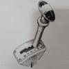
The picture shows how "many" room I have on the shaft - not too much. I tried to press out the shaft to replace it with a longer one but it is impossible, it might be glued inside to the armature.
20250131_093434 (1).jpg 38.43K
1 downloads
There is (was) a nice little machine called "Distrib-U-Scope" I thought I'll copy this one because I could drive the +ve and -ve easily to the LED but it has two belt drive inside which make it complicated...
And as I look the 2nd picture carefully now I can see the -ve contact at the end of the shaft 
Snap On Dist Mach.jpg 72.93K
2 downloads
IMG_5028_2.JPG 195.85K
1 downloads
#69
gaspen
-
- TMF+ Member
-
- 920 posts
One Carb Or Two?
- Location: Budapest
Posted 31 January 2025 - 10:14 AM
More brainstorming
A slip ring on the shaft for the +ve is okay
I figured out that the old diff thrust washer is pretty similiar to a flat slip ring 
Also I took out a smaller brushholder from my bad angle grinder, it just fits nicely under the ring.
20250131_105909.jpg 29.51K
1 downloads
Edited by gaspen, 31 January 2025 - 10:19 AM.
#70
stuart bowes
-

- TMF+ Member
-
- 2,072 posts
Up Into Fourth
- Location: Dagenham
Posted 31 January 2025 - 10:19 AM
intrigued by the sign in the background 'repair your ball marks'
is it a common problem for peoples balls to leave marks ?
(following this engineering project with interest)
Edited by stuart bowes, 31 January 2025 - 10:41 AM.
#71
Spider
-
- Admin
-
- 14,778 posts
Moved Into The Garage
- Location: NSW
- Local Club: South Australian Moke Club
Posted 31 January 2025 - 05:08 PM
Nice work, I am enjoying this
What could be wrong with the power through the bearings ?
I read some articles about this but these negotiate how high currents / voltages damage the balls in the bearings . Here I'll have 12V and tenths or hundredths of ampers only
I can't see you having an issue with the bearings from running the LED current through them, the issue you might have though is maintaining a clean, reliable contact through them as they'll have grease or oil in them. Might be fine, maybe try it and see.
#72
gaspen
-
- TMF+ Member
-
- 920 posts
One Carb Or Two?
- Location: Budapest
Posted 01 February 2025 - 10:14 AM
Nice work, I am enjoying this
What could be wrong with the power through the bearings ?
I read some articles about this but these negotiate how high currents / voltages damage the balls in the bearings . Here I'll have 12V and tenths or hundredths of ampers only
I can't see you having an issue with the bearings from running the LED current through them, the issue you might have though is maintaining a clean, reliable contact through them as they'll have grease or oil in them. Might be fine, maybe try it and see.
Maybe a regular brush attached to the shaft's end will be okay ?
#73
gaspen
-
- TMF+ Member
-
- 920 posts
One Carb Or Two?
- Location: Budapest
Posted 01 February 2025 - 11:01 AM
Meanwhile I found some nice old machines, just for your interest 
Vintage Weidenhoff Distrib-U-Scope, Needs Restoration | eBay
Antique JOSEPH WEIDENHOFF Contact Synchronizer 1930 Car Engine Timing Bakelite | eBay
#74
gaspen
-
- TMF+ Member
-
- 920 posts
One Carb Or Two?
- Location: Budapest
Posted 09 February 2025 - 01:06 PM
I know you are bored but I'm still planning....
I've discarded the previous design and trial fitted the parts to one shaft which attached with a simple coupling.
Well it works on low RPM but that blue coupling isn't really precise, I would not rotate it on higher RPM's
20250201_175234.jpg 56.9K
0 downloads
On the new design all the rotating parts are on one solid shaft. It is a bit more complex but I hope it will be more stable.
dis.JPG 27.98K
0 downloads
I will make the structure from wooden beam brackets
20250209_135412.jpg 50.38K
0 downloads
And finally a question : how should I interpret this diagrams ?
41418 has two breaks in the diagram, which shows where the advabce weights work
But 41254 has three breaks....
20250209_095725 (1).jpg 90.27K
0 downloads
beolvasott_20250209-0929.jpg 74.78K
0 downloads
#75
Spider
-
- Admin
-
- 14,778 posts
Moved Into The Garage
- Location: NSW
- Local Club: South Australian Moke Club
Posted 09 February 2025 - 05:44 PM
Good work !
Really getting somewhere.
Most distributors that have 2 springs will have 3 angles to the 'curve'.
Considering curve A in your diagrams, the first steep part is the lighter primary spring, the lesser angle is the heavier secondary spring and the plateau is when it's reached maximum advance.
Curve B has a sing spring or 2 matched springs.


1 user(s) are reading this topic
0 members, 1 guests, 0 anonymous users


