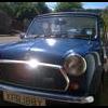
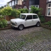
1982 HLE 1000
Hi,
As part of an engine upgrade on my 1982 HLE 1000 I will be fitting a mapable ignition and need some help with the electrical installation.
As part of my initial restoration (pre engine upgrade), I fitted the following:
- Raspberry Pi PC
- 7" TouchScreen
- Sony Radio / CD Player
- Sony XPLOD 1000Watt Amplifier
- Vac Gauge
- Tachometer
- Oil Px Gauge
The Raspberry Pi, Screen Radio were powered by taking a 12v feed from the solenoid and for the lighting are fed from the bottom R/H connector on the fuse box, this is annotated amongst other things as Instrument Panel Lighting. I also fitted an in line fuse with a lower rating for the lighting.
The 12v feed for the Amp comes direct from the battery in the boot via a fuse.
I also fitted a new Bosch 60AH Battery
As part of this engine upgrade I have bought a new 45 Amp Alternator and need to install the following:
- Speeduino NO2C ECU
- Coil Pack
- Pre Engaged Starter Motor
- Lambda Sensor
- AFR Gauge
- Facet Fuel Pump
Whilst researching the installation of the ECU I came across this diagram that shows the Fuel Pump wired via a 40 Amp Relay.

The original version showed all the Injectors wired, which I have removed and modified.
Some initial questions?
Where should I take the 12v supply for the Fuel Pump (into terminal 30 on the relay)
Where should I pick up the Ignition Switch Supply that goes to terminal 86 on the FP relay / the +12v on the ECU and the Coil Pack?
I have been advised to use a relay for the ECU, so how should that be wired?
Where / how should I wire the Lambda Sensor and AFR Gauge?
I understand that I need to calculate the current draw on everything and will get on with that.
Any advice on all of this and wiring the new pre engaged starter (I bought a new solenoid and may do the solenoid mod)?
Any help would be greatly appreciated on all of the above.
Many thanks


