Looking again at John Brown's Defender build he put the motor 2-wires between the 'CDL lock' & 'CDL unlock' outputs of the 10AS (which are pins 2 & 3 of his smaller green connector). Also wired the driver's door lock switch to 'Drivers sill - input' on pin7 of the 10AS larger grey connector.
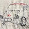
That_20180603_164402.jpg (1600×1095) (bp.blogspot.com)
For the Mini's 5AS unit, the equivalent pins are respectfully: 13 & 11 for the motors and 4 (SILL UP) on the large grey connector (later units also have a smaller white connector for the indicators to flash on lock/unlock).
Checking on the bench, pins 11 & 13 are both are to -ve when inactive - putting a 5w bulb across these pins lights on lock/unlock (current reversal).
For internal driver's CDL operation, referencing the Rover 45 manual:
Door latches - General
Each door has a sill button attached to the latch
mechanism. The sill buttons remain accessible in
the locked and unlocked conditions. The driver’s
door sill button when pressed, will lock all doors.
Pulling the driver’s door sill button upwards unlocks
all doors. Operation of any passenger door sill
button will lock or unlock the individual door only.
Needs more bench testing as I have been unable to get it to work as yet - pin 4 SILL UP, pin 19 SILL DOWN, both to -ve when active.
Edited by Deeppockets, 15 March 2021 - 02:58 PM.


