Was linked to this from another site, and just read through your original post too, where you asked for data. This is dead impressive, massive props, and i hope all those know it all's in your first post see this. 

It Started As An Intellectual Exercise
Started by
Trog
, Jan 17 2020 11:01 PM
107 replies to this topic
#31

JetBLICK
-

- Members
-

- 1,222 posts
One Carb Or Two?
- Local Club: myspace.com/worcesterretro
Posted 20 January 2020 - 04:52 PM
#32
Stealth72
-

- Just Joined
-
- 25 posts
Passed Test
- Location: Marshland St James, Norfolk
Posted 20 January 2020 - 07:33 PM
This is fabulous stuff @Trog, thanks for posting it up.
When/where did you study Automotive Engineering/Design?
When/where did you study Automotive Engineering/Design?
#33
mab01uk
-
- Members
-
- 12,405 posts
Moved Into The Garage
- Local Club: Mini Cooper Register
Posted 20 January 2020 - 08:08 PM
Posted a link to your 8 port head and this thread on the Mk1 Forum Trog, hope you don't mind.....the Mk1 members are also very impressed by your amazing work!
http://mk1-forum.net...php?f=5&t=27467
Edited by mab01uk, 20 January 2020 - 08:09 PM.
#34
Trog
-
- Just Joined
-
- 91 posts
Stage One Kit Fitted
Posted 20 January 2020 - 11:26 PM
Thanks for all the encouragement! I am writing the next installment at the moment but thought I would answer a few questions and add a little update:
I studies Automotive Engineering Design at Coventry University in the late '90's
mab01uk, happy for you to repost as much as you want!
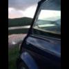
No I haven't done any flow testing yet, Exhaust ports are fairly standard and the inlets are so open I felt there wasn't a great deal of point! You can see the valve from the plenum chamber:
 20200119_140647.jpg 50.77K
0 downloads
20200119_140647.jpg 50.77K
0 downloads
This is for fast road use (at the moment!) can't see any race applications for it?
Yes I have a Dalek in the garage (Called Arnie; he's an ex-terminator!) I have incurable OMD (Obsessive Making things Disorder, also known as fixitis) so always have to have some crazy project on the go!
Will I be making more? Well maybe, if people wanted them!
For those worried about the Dipstick; I made one, $4 for a bit of ally tube & $2 for a dipstick from the scrapyard:
20200121_071241.jpg 71.45K
1 downloads
20200121_071344.jpg 70.58K
4 downloads
20200121_071411.jpg 43.68K
4 downloads
Finally for those wanting more info/images of the castings etc,; well you will have to wait for later installments!
#35
Norway Thomas
-

- Just Joined
-
- 18 posts
Learner Driver
- Location: Fiskarstrand
- Local Club: Norsk Mini Cooper Club.
Posted 21 January 2020 - 10:26 AM
OK I will do some posts going through the whole process.
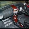
In the mean time some images of the dry build:
Head on, knock sensors, cam position sensor and "Multi purpose bracket"
Fuel injectors and rail (the observant among you may notice the fuel rail is 3D printed as I wanted to do a full dry build with the injectors before getting it made!):
Coil pack and fuel pressure regulator:
Inlet manifold/plenum assembly:
So has anyone spotted the deliberate mistake... No it's not that I will have to remove the inlet manifold to change the plugs. I can't get to the dip stick!!! So my next task is to make a remote one. SC do one but by the time I have covered the cost of posting to Australia I think I can make one myself for a lot less money.

Is the fan fitted backwards?
#36
cooperd70
-

- TMF+ Member
-
- 726 posts
One Carb Or Two?
- Location: London
Posted 21 January 2020 - 10:31 AM
Is the fan fitted backwards?
That's what I thought. Smooth side should be facing the block, ridged side facing the rad.
#37
Norway Thomas
-
- Just Joined
-
- 18 posts
Learner Driver
- Location: Fiskarstrand
- Local Club: Norsk Mini Cooper Club.
Posted 21 January 2020 - 10:36 AM
Is the fan fitted backwards?
That's what I thought. Smooth side should be facing the block, ridged side facing the rad.
My thoughts too.
My question would be what camshaft is used? I would guess that it is the same as an Ardun 8 port.
#38
Trog
-
- Just Joined
-
- 91 posts
Stage One Kit Fitted
Posted 21 January 2020 - 11:08 AM
OK yes the fan was on backwards for those pictures!
Yes the 8 ports have a unique cam...
#39
cooperd70
-
- TMF+ Member
-
- 726 posts
One Carb Or Two?
- Location: London
Posted 21 January 2020 - 12:36 PM
OK yes the fan was on backwards for those pictures!
Yes the 8 ports have a unique cam...
I didn't want to say anything as it's obvs that you're def not a newbie to the A/A+ engine ??
Had noticed that there were just a couple of bolts holding it on so assumed that it was popped on for the photos ?
Great work by the way ?
#40
Spider
-

- Admin
-
- 14,821 posts
Moved Into The Garage
- Location: NSW
- Local Club: South Australian Moke Club
Posted 21 January 2020 - 05:59 PM
I'm loving this.
The work involved here is immense and I take it you did use computer aids for the design ?
Was it cast locally ?
#41
Trog
-
- Just Joined
-
- 91 posts
Stage One Kit Fitted
Posted 21 January 2020 - 11:51 PM
Chapter 2 “Hang on lads I’ve got a great idea”
Just to clarify all the design work was done on CAD, using CATIA.
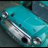
I have been looking for original drawings/CAD for the head for a long time; those that have the data are unwilling to share (Which seems a bit dog in a manger to me but there we go!). So, I had to go to plan B which was to 3D scan a head. Luckily for me we have a scanner at work so scanning the head was a “learning exercise” for me!
Original Head.jpg 56.66K
5 downloads
Scan Data 1.JPG 26.78K
3 downloads
Scan Data 2.JPG 28.24K
1 downloads
This was used to extract the “primary datums” for the design. These are the parts that will be common with the original 5 port. Head stud, rocker pillar studs, & push rod holes, mating faces and bore centres. As well as the architecture of the rocker area.
Datums 1.JPG 37.68K
1 downloads
Next, I modelled combustion chamber, exhaust port and an initial inlet port. It’s worth noting here that the inlet port position is driven by the head stud on the No4 cylinder… The Arden actually has different ports for 1,2, &, 3 cylinders to 4, however I wanted a common port shape for all 4 cylinders as this would help to make the engine tuning etc. easier. The exhaust is, at this stage, a copy of the No1 cylinder port as I needed a “Peg in the ground” to work around before I looked in to down drafting (Or is that up drafting as it’s the exhaust?). An initial spark plug hole was modelled. It should be noted that there was no chance of using a standard plug, so I modelled around a 10 mm 1-inch thread length plug. Valve guide and spring seat positions were also added. Finally, I put an inlet manifold mounting face in. This is the same as the Arden face (so I could use Arden gaskets!) Rotational orientation of these would be tuned throughout the design process. I wanted them as vertical as possible so the bolt pattern would have a good spread to support the heavy manifold. The result you see is the compromise driven my other factors such as the injectors and spark plugs.
Chamber Ports and Plug.JPG 35.24K
2 downloads
Including Inlet Face.JPG 34.16K
2 downloads
Taking Shape.JPG 40.6K
0 downloads
Cutter Top.JPG 32.85K
2 downloads
As you can see very quickly things are taking shape, so the next stage is to start “blocking” things up. I used a material minimum thickness of 6 mm, so everything developed so far was thickened to this to start building a solid model.
What followed was a lot of iteration, very hard to show with images. I need to maintain a minimum wall thickness of 6 mm, while also maintaining a reasonable water jacket.
The injector position had to be developed. Old school thinking on the injectors it that they should point at the back of the valve, more modern thinking drives the injectors back up the inlet track, as modern injectors atomise the fuel better. As the injectors are in the head, I tried to get them as close to pointing at the valve as possible. This area of the head was the biggest challenge; getting the port, inlet flange, spark plug and injector boss to all fit around the rocker cover and head studs. So, there are of course compromises. Injector position is good, but not perfect, it is also leant over my 5 degrees which makes for more complicated machining on the injector rail. The spark plug is a very snug fit and the inlet flange bolts are rotated more than I would like.
Port.jpg 22.74K
4 downloads
Exhaust port design was also studied, I have no images of this, but it soon became apparent (as I suspected) that up-drafting the ports was not really a viable option. Due to the push rods & rockers and rocker cover I would only be able to get about 3-5 degrees. And even that would compromise the water jacket. Making a unique rock cover (like the Pinion head) would help but that was beyond my design remit. Therefor I decided to keep a “carry-over” design. I would be able to use an off the shelf 8 port exhaust manifold, not a bad idea when you think how much else I needed to design and engineer!
Pinion.gif 27.43K
4 downloads
At the front of the head I wanted to copy the 5 port head and run the water jacket under the plugs to aid coolant flow. To do this drove the head a long way forward as the plugs are at a much shallower angle to get under the inlet ports. You can see the “chin” on the front of the casting. This also allowed me to get water to all 8 of the front water jacket holes in the top of the block. I did not want to block any of these off or be forced to machine channels into the face of the head, as seen in some 7 port designs.
Similarly, the Oil gallery follows a similar route to the 1275 casting, but with one more drilling due to the reduced length of the head (No thermostat housing)
Couple of points about the model developed at this time: I did develop a high-level concept of the tooling design, but the model has no draft angles and many overhangs. The reason for this will become apparent later. I am also modelling a finished machined head. There is about 3-4 months covered in this chapter, and many many many hours of CAD.
Model 1.JPG 50.26K
0 downloads
Model 2.JPG 48.45K
2 downloads
Model 3.JPG 42.62K
2 downloads
(Water jackets were in the model, just not in these images for some reason)
With an initial design complete my next step was to start up by trusty ($200) 3D printer and print a full-size mock-up to do some form, fit and function testing…
3D 002.jpg 32.79K
4 downloads
3D 001.jpg 30.94K
2 downloads
So not sure if that’s too verbose or leaves too many questions! Let me know…
#42
Turbo Phil
-
- TMF+ Member
-
- 2,426 posts
Up Into Fourth
- Location: Cumbria
- Local Club: Cumbria Classic Mini Club
Posted 22 January 2020 - 12:07 AM
This is great stuff, hats off.
Are the valve spacings standard ? And is the exhaust port modelled straight off a 5port head end port ?
Phil.
Are the valve spacings standard ? And is the exhaust port modelled straight off a 5port head end port ?
Phil.
Edited by Turbo Phil, 22 January 2020 - 12:10 AM.
#43
l_jonez
-
- Members
-
- 1,453 posts
One Carb Or Two?
- Local Club: south wales mini club
Posted 22 January 2020 - 12:23 AM
Love this more than I can explain!
Keeping a very close eye on this as I'd be interested if you decide to sell some
#44
Spider
-
- Admin
-
- 14,821 posts
Moved Into The Garage
- Location: NSW
- Local Club: South Australian Moke Club
Posted 22 January 2020 - 08:20 AM
Gobsmacked !
Perfect or otherwise - I sincerely appreciate the hours in this. I know everything always has compromises, but it looks to me like you've carefully considered them and worked around them as best as possible.
Loads of thought and practical considerations.
Wow !
Keep it coming !
#45
Pete - W.Sussex
-

- Just Joined
-
- 91 posts
Stage One Kit Fitted
- Location: West Sussex
Posted 22 January 2020 - 09:31 AM
Completely and utterly speechless........ there must be a book to come!
Keep it coming and thank you.


1 user(s) are reading this topic
0 members, 1 guests, 0 anonymous users


