
Earthing the brown/yellow at the alt should not extinguish the lamp.
The lamp goes out when the alternator is charging and putting over 12V onto this wire.

Crazy About Mini's


Posted 05 January 2019 - 06:26 PM
Earthing the brown/yellow at the alt should not extinguish the lamp.
The lamp goes out when the alternator is charging and putting over 12V onto this wire.
One Carb Or Two?

Posted 05 January 2019 - 07:13 PM
As above really. The lamp is fed by 12V from behind the instrument cluster. The other wire then goes to the alternator. Before you start the car you have 12V at one side of the lamp and 0V at the other. (The alternator isn't doing anything). When the car is started and the alternator is charging, you have 12V at both sides of the lamp. There is 0 potential difference (another way of stating Voltage), so the lamp goes out.
Speeding Along Now
Posted 05 January 2019 - 08:02 PM
Crazy About Mini's
Posted 05 January 2019 - 08:35 PM
Speeding Along Now
Posted 05 January 2019 - 09:00 PM
Up Into Fourth

Posted 05 January 2019 - 09:16 PM
Speeding Along Now
Posted 05 January 2019 - 09:58 PM
Speeding Along Now
Posted 05 January 2019 - 10:18 PM
Silly question, but are you sure the alternator actually works properly? No good chasing a wiring problem if that isn't where the fault lies.
Speeding Along Now
Posted 06 January 2019 - 12:39 PM
Up Into Fourth
Posted 06 January 2019 - 02:23 PM
Edited by KTS, 06 January 2019 - 02:25 PM.
Speeding Along Now
Posted 06 January 2019 - 09:13 PM
Crazy About Mini's
Posted 06 January 2019 - 09:56 PM
From what I understand brown and yellow wire goes to the red ignition light. once the charge is equalised across that wire it would go out because it has 12v both sides? but if it is wired wrong the alternator would not be triggerred into charging the battery. I'm going to look back at the pics I posted of the wiring of the dashboard. I think the yellow and brown wire should go to the red light and then from the light to the voltage regulator.
Speeding Along Now
Posted 06 January 2019 - 10:43 PM
Speeding Along Now
Posted 07 January 2019 - 07:26 AM
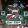
I'm now a little confused. The main wiring I have is per the attached diagram. It all seems to work except the battery clearly isnt charging. 12.5 volts at the battery with engine running.
Which wire controls the charging of the alt? The brown and blue one at the main terminal? Or the brown and yellow one at the indicator light? Before I take all the dash apart will the Alt only charge if there is 12v both sides of the alt charging light??? Or is that just an indicator and the alt charges regardless if the brown and blue is connected. Apologies if I've misunderstood but I appear to have conflicting comments. It would seem to make sense that unless the charge light is operating correctly the alt wont charge. If that's the case can I run a separate live to the other side of the charging light to compmete the necessary circuit. I wonder if my temp gauge will also be affected if the wiring in the stabiliser is off or missing something. Cheers.
 20190106_130911-1209x1612.jpg 25.36K
1 downloads
20190106_130911-1209x1612.jpg 25.36K
1 downloads
Speeding Along Now
Posted 07 January 2019 - 11:09 AM
I found this in another post on the forum.
It's true. With MOST Lucas alternators you have to have a functioning warning light or the alternator will not charge.
I'd like to make a few minor corrections to Phaeton's explanation. When you turn the ignition switch to the "run" position, current from the switch flows through the warning light to the field coils in the alternator. The "other side" of the field coils are connected to earth. When you turn switch, you are providing power to energize the alternator field coils. The warning light turns "on" because it has a path to earth through the field coils. Once the engine starts, the alternator starts producing electricity and the internal electronics "self energize" the field coils by providing voltage to the internal connection point where the charge warning light wire connects. When that happens (when the alternator brings the internal connection of the small spade lug up to charging system voltage) both sides of the warning light are "high" and there is no path to ground for the warning light... so it goes out.
If the warning lamp is missing or burned out, the field coils will not energize and therefore, the alternator never starts making electricity. OK... that said, there are many alternators that have some residual magnetism in the steel parts the field coils are on. SOME of those alternators will have enough magnetism that a really strong rev of the engine (like sudden burst of 4k RPM or more) can "kick in" the electronics and the alternator will start charging. This is the exception, not the rule, and you shouldn't count on it working every time. Another thing to keep in mind is that you cannot use an LED light (by itself) for the charge warning light. The LED will NOT let enough current flow through it. An LED will light up without allowing the field coils to energize.
You measured 12.5V with the engine running. Take the same measurement with the engine off. You should see about a 1.5V increase in the potential across the battery when the alternator is working. Most charged batteries will measure about 12.5V at rest so you should be looking for 14V or more across the battery for a working alternator to be charging.
So that answers the question as to if you have to have the charging light working. I think I need to take the dash out and see if either the bulb for the ignition light is earthed which it shouldn't be and if the wire coming from the voltage regulator is actually live with 12v which I understand it should be? If my wiring as shown in previous post is all fine. I think it probably is it would seem to be down to the wiring of the ignition light. I wouldn't be surprised if the issue was there because I changed a lot of wires over from the original gauges. Can someone point out any glaring errors in this statement or in the wiring diagram above.
Thanks all.


Mini Technical Sections →
Problems, Questions and Technical →
Understanding The Starting System / AlternatorStarted by Jaybraham , 18 Feb 2025 |
|

|
||
Mini Technical Sections →
Problems, Questions and Technical →
Identifying Wiring Diagram/loomStarted by Jaybraham , 02 Feb 2025 |
|

|
||
Are Auxiliary Switches (Fog,hazard Etc) Supposed To Be Backlit At Night?Started by leehine54 , 31 Jan 2025 |
|

|
||
Mini Technical Sections →
Problems, Questions and Technical →
Which Ignition Coil?Started by daddums , 27 Jan 2025 |
|

|
||
Mini Technical Sections →
Problems, Questions and Technical →
Air Conditioning For 1960 Mk 1Started by Oldkartracer , 17 Jan 2025 |
|

|
0 members, 2 guests, 0 anonymous users


