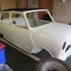
A big thanks for your drawings Mike. I'm restoring a 1969 MKII Cooper S and am now installing a new wiring harness. Your diagram is a great help and much clearer to understand than other diagrams I have. Great stuff, thanks Mike.
#61

Posted 13 October 2020 - 08:23 PM
#62

Posted 25 October 2020 - 05:14 PM
Being the old car it is parts have been used from elsewhere. I have narrowed it down to two cars
1988 Austin mini Mayfair auto which has been converted to manual 1275.
1986 Austin mini piccalilli parts have been used from this car.
Sorry for the long message but can someone point me.in the right direction to what diagrams I should look at
Thanks
#63

Posted 18 November 2020 - 11:25 PM
#64

Posted 19 November 2020 - 12:57 AM
I have an Austin mini ritz 1985, which diagram should I use? I cannot see anything close to that on the list. Thanks.
What ever year is closest but earlier.
#65

Posted 17 December 2020 - 04:40 PM
I added colour and a parts list to the Inno Cooper 1300 Export wiring diagram to make following the cables easier.
Attached Files
#66

Posted 29 March 2021 - 12:43 PM
Hi, I have a Japanese 1991 Mini Cooper (carburettor) re-imported back to the UK.
I was wondering if anyone knows of a wiring diagram for one.
I want to remove all residual wiring associated with the aircon and catalyst sensor and anything else unique to Japanese models. Even if someone knows of the wiring colours associated with these items
It seems difficult getting information on the exact specification of these models.
Thanks, Mike
#67

Posted 17 July 2021 - 08:57 PM
thankyou for the hard work
#68

Posted 16 August 2021 - 05:23 PM
These diagrams are incredibly helpful. However I have a question. I have a single central instrument which only has one indicator tell-tale. The wiring diagram shows the bulb is connected between the left and right feeds, but it will only get power from one at a time obviously. Where is it earthed to? I can’t work out how the circuit is completed. The unused side (left or right) must somehow get earthed but for the life of me I can’t work out how!!
#69

Posted 16 August 2021 - 06:14 PM
These diagrams are incredibly helpful. However I have a question. I have a single central instrument which only has one indicator tell-tale. The wiring diagram shows the bulb is connected between the left and right feeds, but it will only get power from one at a time obviously. Where is it earthed to? I can’t work out how the circuit is completed. The unused side (left or right) must somehow get earthed but for the life of me I can’t work out how!!
The lamp holder is different to the rest of the holders.
#70

Posted 16 August 2021 - 09:38 PM
These diagrams are incredibly helpful. However I have a question. I have a single central instrument which only has one indicator tell-tale. The wiring diagram shows the bulb is connected between the left and right feeds, but it will only get power from one at a time obviously. Where is it earthed to? I can’t work out how the circuit is completed. The unused side (left or right) must somehow get earthed but for the life of me I can’t work out how!!
The tell-tale earths through the unpowered indicator circuit - which is why if you use an LED bulb for the tell-tale, it will only work in one direction
#71

Posted 30 August 2021 - 01:52 PM
Thanks for that, I assumed it did but cannot quite work out how, will just need to wire it up and test it!
I'm a bit over a year late, but just for completeness... The green dash light has much higher resistance than the front & rear indicator bulbs it's using as an earth. Enough current flows to light the 2.2W green telltale, but it's nowhere near enough to warm even one of the 21W indicator bulbs.
Edited by Ethel, 30 December 2022 - 12:59 PM.
OCD?
#72

Posted 04 March 2022 - 08:42 AM
Just found this, brilliant work thank you!
#73

Posted 31 July 2022 - 03:07 PM
Hello to all, please, which diagram is correct for Austin Mini Clubman estate, year 1980, LHD. I am confused, my clubman have 4 fuses in box + 2 inline fuses, here have i found only diagram with 2 fuses in box and 2 inline. Anbody who can help me??? I have problem with my Clubman, no working hazard lights and interior light uder roof, here is problem with inline fuse connection, and next problem fuel gauge and cooling gauge on dash board working not, here can be problem with wire connection, fuel sender and temperature transmitter are changed for brand new. Thanks for help.
#74

Posted 12 January 2023 - 08:41 AM
Guys would ye have a wiring diagram for a 1994 mini Sprite . Thanks !
I have a 1993 sprite and a 1994 Italian job. They are both the same looms(have multiple unused wires(spot/fogs, additional rear wiring)
A set of inline fuses for the front lights
A set of inline fuses(behind carb) as per carb cars.
Hi could you send me Italian job loom diagram
#75

Posted 14 June 2023 - 08:20 PM
http://www.minispare...|Back to search
Also tagged with one or more of these keywords: electrical
Mini Technical Sections →
Problems, Questions and Technical →
1986 Mini Chelsea - Main Beam IssueStarted by Dominic1998 , 25 Apr 2025 |
|

|
||
Mini Technical Sections →
Problems, Questions and Technical →
Understanding The Starting System / AlternatorStarted by Jaybraham , 18 Feb 2025 |
|
|
||
Mini Technical Sections →
Problems, Questions and Technical →
Identifying Wiring Diagram/loomStarted by Jaybraham , 02 Feb 2025 |
|
|
||
Are Auxiliary Switches (Fog,hazard Etc) Supposed To Be Backlit At Night?Started by leehine54 , 31 Jan 2025 |
|
|
||
Mini Technical Sections →
Problems, Questions and Technical →
Which Ignition Coil?Started by daddums , 27 Jan 2025 |
|

|
1 user(s) are reading this topic
0 members, 1 guests, 0 anonymous users


