Hi folks.
I have a 1293 metro which has two engine breathers one on the crack case at the rear of the engine clutch side and one on the front crank case
Now there is hoses coming from each breather and the previous owner had both of then attached to the catch can which I think is incorrect.
So how should these hoses be connected


Engine Breathers
Started by
Boombastik
, Jan 08 2017 02:38 PM
30 replies to this topic
#2

Dusky
-

- Members
-

- 5,322 posts
Crazy About Mini's
- Location: Belgium
Posted 08 January 2017 - 06:36 PM
I have mine into a Y piece then into the carb.
#3
Boombastik
-
- Noobies
-
- 7 posts
Just On Tickover
- Location: Aberdeen
Posted 08 January 2017 - 06:41 PM
I have mine into a Y piece then into the carb.
Any chance you can post a pic please
#4
panky
-

- Members
-
- 1,790 posts
Camshaft & Stage Two Head
- Location: Cheshire
Posted 08 January 2017 - 06:56 PM
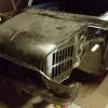
Minispares have them, just got one for my Cooper as the old one snapped.
It's shown to the left of the rocker box in this pic, the pipe from the breather on the timing chain cover is hidden behind the rocker box

#5
Boombastik
-
- Noobies
-
- 7 posts
Just On Tickover
- Location: Aberdeen
Posted 08 January 2017 - 07:47 PM
Thanks for that. Perfect cheers
#6
Boombastik
-
- Noobies
-
- 7 posts
Just On Tickover
- Location: Aberdeen
Posted 10 January 2017 - 08:20 PM
If using a catch can how should that be plumbed in to the above system in the pic
#7
paulrockliffe
-

- Members
-
- 1,763 posts
Camshaft & Stage Two Head
- Location: Durham
Posted 10 January 2017 - 09:38 PM
The proper catch tanks have a nozzle on the top that plumbs to the carb.
I asked a question a few months ago about oil leaks, it was pointed out that without plumbing to the carb the engine crankcase pressure is higher and the engine prone to high pressure spots, which can cause leaks. I've plumbed my breathers to the carb.
It's important to realise that the engine isn't just venting into the carbs, the flow through the carbs is sucking the pressure out of the crankcase.
#8
Ricewind
-

- Noobies
-
- 61 posts
Stage One Kit Fitted
- Location: South Molton Devon
Posted 17 January 2017 - 04:41 PM
Reducing the crankcase pressure is a good thing, not just to help stop oil leaks, it also reduces the energy loss through windedge. Inside the crank case air is constantly being forced from underneath the two outside pistons to the underside of the inside pistons and back. It is surprising how much energy is lost through this reciprocating air movement at high engine speeds. The effect is exacerbated by having a free flowing air filter. With little resistance to flow the vacuum in the inlet manifold is only marginally lower than atmospheric and fails to do a good job of evacuating the sump gasses.
What I did to remedy this problem was to obtain a couple of non-return valves the type you used to find on the vacuum pipe that goes from the inlet manifold to the servo brake unit on some cars. Next I welded a short piece of 10mm pipe onto the exhaust pipe just past the last "Y" joint at about 30o so that it acts like a venturi and creates a vacuum in the smaller pipe when the gas flow is sufficiently high enough. I then connected silicone pipe from their to a "Y" connector that connected vacuum hose from the inlet manifold and another pipe to the top of the catch can (or ideally a knockout pot). I then fitted the non return valve, One between the "Y" connector and the inlet manifold so that gasses can only go into the manifold and the another in the pipe from the "Y" connector to the exhaust pipe so as gasses can only go towards the exhaust.
The idea is at low engine speeds the vacuum in the manifold is high and so this evacuates the sump. at higher engine speeds the exhaust creates an even higher vacuum and takes over. You have to make sure that oil cap has no vent (I sealed mine up) and the dip stick has an "O" ring type seal. And under no circumstances do you want to make the mistake that I made and put the manifold non-return valve in the wrong way round. When first testing it when I reached a certain speed a big white cloud came out of my exhaust pipe. With valve the wrong way round the exhaust drew fuel air mixture out of the manifold producing the white cloud that followed me. Luckily I realized what was happening and pulled over quickly before it ignited like a JATO rocket or propelled my exhaust pipe like a sidewinder missile.

#9
Steve220
-

- TMF+ Member
-
- 5,044 posts
Crazy About Mini's
- Location: Shropshire
- Local Club: BMC
Posted 17 January 2017 - 05:22 PM
Nice idea - what does it do to your emissions on fast idle when it comes to MOT time?
#10
Ricewind
-
- Noobies
-
- 61 posts
Stage One Kit Fitted
- Location: South Molton Devon
Posted 17 January 2017 - 06:48 PM
Nice idea - what does it do to your emissions on fast idle when it comes to MOT time?
It should not make any difference as at fast idle the inlet manifold will have the lower pressure and the, exhaust side, non-return valve will be shut. I never had a problem with mot back in 2004 when I last had it. I will be doing the same thing on my latest 1380cc project only I shall probably make a proper knock out pot, I have a nice aluminium container that would look good although I think the catch can works well enough as there should not be too much gas throughput. Another good idea is to put a vacuum gauge on the system as this can tell you if you have a problem with the engine. A good vacuum is a good indication that that there is no blow by etc. I shall get a sphygmomanometer (blood pressure gauge) off of eBay for about £15 as the gauge measures both positive and negative pressure (relative to atmospheric).
#11
Turbo Phil
-

- TMF+ Member
-
- 2,426 posts
Up Into Fourth
- Location: Cumbria
- Local Club: Cumbria Classic Mini Club
Posted 17 January 2017 - 06:50 PM
The idea of using the exhaust to draw it into a catch can looks nice.
If you're after performance the last thing you want is these fumes being sucked back into the engine via the carb. These oily fumes will drop fuel octane and reduce charge density, neither of which are good for power.
Phil.
If you're after performance the last thing you want is these fumes being sucked back into the engine via the carb. These oily fumes will drop fuel octane and reduce charge density, neither of which are good for power.
Phil.
#12
Spider
-

- Admin
-
- 14,838 posts
Moved Into The Garage
- Location: NSW
- Local Club: South Australian Moke Club
Posted 17 January 2017 - 06:50 PM
Is that a Catch Can or the Oil Separator in that well presented drawing?
#13
Swift_General
-
- Members
-
- 871 posts
One Carb Or Two?
- Location: England
Posted 17 January 2017 - 07:30 PM
Nice idea. I also initially thought there may be an issue with emmisions, but thinking about it the test is initially conducted only at tick over when clearly the pressure in the inlet manifold will be much lower than at the exhaust. Just be mindful thought that if your car is '72 onwards the above, catch tanks and the like may fall foul of C&U regs.
#14
Steve220
-
- TMF+ Member
-
- 5,044 posts
Crazy About Mini's
- Location: Shropshire
- Local Club: BMC
Posted 18 January 2017 - 06:02 AM
Nice idea. I also initially thought there may be an issue with emmisions, but thinking about it the test is initially conducted only at tick over when clearly the pressure in the inlet manifold will be much lower than at the exhaust. Just be mindful thought that if your car is '72 onwards the above, catch tanks and the like may fall foul of C&U regs.
Run catch tanks in all my performance cars, all sailed through MOT's. Including the VTA ones I've had on the Evos.
#15
Ricewind
-
- Noobies
-
- 61 posts
Stage One Kit Fitted
- Location: South Molton Devon
Posted 18 January 2017 - 07:28 AM
Is that a Catch Can or the Oil Separator in that well presented drawing?
It is meant to be the oil separator that is standard fitting on my engine at least. It does the same thing as a catch tank aided by a cause wire basket thing inside. A knock out pot or catch tank tends to be bigger and relies on a swirl effect, a bit like a Dyson vacuum cleaner only less sophisticated, any breather pipes enter the side at an angle and oil drain comes out the bottom back into the engine and the fumes exit the top like in the diagram.


1 user(s) are reading this topic
0 members, 1 guests, 0 anonymous users


