Jump to content


Photo
- - - - -

Rev Counter Help


  • Please log in to reply
16 replies to this topic

#1 coopdog

coopdog

    Up Into Fourth

  • TMF+ Member
  • PipPipPipPipPipPipPipPipPip
  • 4,506 posts
  • Location: South Wales

Posted 19 August 2015 - 12:14 PM

Hi guys

I have a 1275gt 3 clock fitted to my car which all the clocks work

I have changed to a nodiz electronic ignition system and want to get my rev counter to work,I have made the coil driver with 3 resistors with the output from the two coil wires going into two resistors then those two resistors going into one with that output going to the coil

Now the rev counter works but only to 2300rpm,
I spoke to nodiz and pretty much just hurried me off the phone and told me to buy the one off trigger wheels and that will work, fitted it and the rev counter only works until 3000rpm (£14 an I'm a bit annoyed)

I told him about this and this was his response,

"Hi,

Sorry I never saw it.

TW reply is incorrect - it turns a W/S coil firing into a tach signal, regardless of what drives the coils.

Our tacho signal works with 99% of tachos, its a standard 12v Sq Wave, without knowing how your tacho is originally driven, it will be hard to get round it.

If you can get this information then we can help, without it, it will be a struggle.

Thanks
Matt"

Now I'm not clued up on how resistors work, all I can think of is that the resistor is capping the voltage at a too low a voltage and I nee a resistor with a higher range? can any of you guys help me out with this?

Thanks callum

Edited by coopdog, 19 August 2015 - 12:15 PM.


#2 WiredbyWilson

WiredbyWilson

    WiredByWilson

  • Traders
  • PipPipPipPipPipPipPipPipPipPip
  • 5,004 posts
  • Location: Kent
  • Local Club: WiredByWilson

Posted 19 August 2015 - 12:26 PM

Never had any issues with Tacho on MJ, in fact we fit two tacho drivers in out looms to help buyers avoid this exact problem.


With Nodiz - do you know the output from Nodiz? If the ecu won't power the tacho you should be able to patch your coil driver to the wiring for the coil directly?

But you say you have made the coil driver - have you used the two different diodes required for it to work correctly - some make the mistake thinking all three are the same?


Will help as much as possible but we dont deal with Nodiz as we have excellent support from Autosprtlabs and Trigger-Wheels on the MegaJolt Systems.


David

WiredbyWilson


#3 coopdog

coopdog

    Up Into Fourth

  • TMF+ Member
  • PipPipPipPipPipPipPipPipPip
  • 4,506 posts
  • Location: South Wales

Posted 19 August 2015 - 03:37 PM

Never had any issues with Tacho on MJ, in fact we fit two tacho drivers in out looms to help buyers avoid this exact problem.
 
With Nodiz - do you know the output from Nodiz? If the ecu won't power the tacho you should be able to patch your coil driver to the wiring for the coil directly?
But you say you have made the coil driver - have you used the two different diodes required for it to work correctly - some make the mistake thinking all three are the same?
 
Will help as much as possible but we dont deal with Nodiz as we have excellent support from Autosprtlabs and Trigger-Wheels on the MegaJolt Systems.
 
David
WiredbyWilson


to be honest I wish I bough mj, the customer support for nodiz is terrible!!!

I'm currently on my way home from the south of France and will post the wiring diagram I used.

And yeah I wired up the tacho driver from the two coil signal wires, so each wire than has one resistor on each which is the same, then I soldered both legs of the output side of the resistors onto the input leg of another different resistor and that output goes to the tacho.

But as I said I also bought the coil driver from the trigger wheels website itself, the one for £14 and that was slightly better, but still isn't perfect :(

#4 WiredbyWilson

WiredbyWilson

    WiredByWilson

  • Traders
  • PipPipPipPipPipPipPipPipPipPip
  • 5,004 posts
  • Location: Kent
  • Local Club: WiredByWilson

Posted 19 August 2015 - 04:30 PM

Give me a shout when you are back and we'll get you sorted out.

#5 dklawson

dklawson

    Moved Into The Garage

  • TMF+ Member
  • PipPipPipPipPipPipPipPipPipPipPip
  • 10,923 posts
  • Name: Doug
  • Location: Durham, NC - USA
  • Local Club: none

Posted 19 August 2015 - 04:31 PM

I don't know which tach was fitted to a '73 Mini.  Can you look at it and see the letters RVI or RVC on the face?  If not, does the rear connection use 1 or 2 bullet connectors?


RVI tachs do not like electronic ignitions.  There are some possible workarounds for RVI tachs but they are not handled by resistors additions.


#6 coopdog

coopdog

    Up Into Fourth

  • TMF+ Member
  • PipPipPipPipPipPipPipPipPip
  • 4,506 posts
  • Location: South Wales

Posted 19 August 2015 - 07:11 PM

it says RVC on the face and has one bullet connector and one spade connector


this is the wiring diagram i used

551535_477256755656975_1659082328_n-1.jp


this is a spare rev counter i have, the one fitted to the car is exactly the same


tumblr_ntcfv2I5OH1qco8kdo3_500.jpg


tumblr_ntcfv2I5OH1qco8kdo2_250.jpg


tumblr_ntcfv2I5OH1qco8kdo1_250.jpg


#7 coopdog

coopdog

    Up Into Fourth

  • TMF+ Member
  • PipPipPipPipPipPipPipPipPip
  • 4,506 posts
  • Location: South Wales

Posted 19 August 2015 - 07:17 PM

also this is a vid so you can see the exact problem


#8 dklawson

dklawson

    Moved Into The Garage

  • TMF+ Member
  • PipPipPipPipPipPipPipPipPipPipPip
  • 10,923 posts
  • Name: Doug
  • Location: Durham, NC - USA
  • Local Club: none

Posted 19 August 2015 - 08:36 PM

In your first post you said that Nodiz told you that their output is a standard square wave 12V pulse.  The online manual I found (link below) says on page 10 that the output is 5V and that you need the diode pack to generate a 12V pulse.  

Nodiz Manual


The diode pack solution they are proposing seems odd to me.  There are other ways to handle this.  Are you at all comfortable soldering and making your own circuits?  If so, you an rig up a mosfet or transistor to handle the signal switching.  Basically, the transistor (or mosfet) is an electronic switch.  By connecting it to the 5V tach output of the Nodiz, you can turn the transistor on and off, switching 12V.  That 12V signal would in turn be connected to your tach's bullet connector.  In short, you would use the 5V output of the Nodiz to turn on and off a 12V signal supplied to the RVC tach.  What they are doing with the coilpack A and B wires escapes me.


See the general schematic below.  The 5V supply would come into the transistor or mosfet from the left.  The "load" would be something like a 100k Ohm resistor.  You would connect the "low" side of the resistor to the bullet connector on your tach to get a signal.  You would need to add a couple of other resistors to the circuit to make sure the transistor or mosfet switched completely off and to insure when it is turned off the voltage is zero/low... but this would be a simple addition to what is shown below.

02125x01.png


#9 motorsportelectronics

motorsportelectronics

    Stage One Kit Fitted

  • Traders
  • PipPipPip
  • 54 posts

Posted 23 August 2015 - 10:55 AM

The rev2 system he uses indeed puts out a 12V signal.


To say our support is poor is simply unfair. He actually argued with us about wasted spark / firing orders and elsewhere on the forum other members illustrated where he was wrong. He even came to my house (I was not in the office that day) and I checked his NODIZ there for him. (low and behold it was fine!)


You seem to ask LOTS of questions on the forums, which is fine, but some of them indicate not reading the manuals properly, or simply getting far too involved in something which you don't fully understand, which of course will lead to frustration, and ultimately, complaining about the system.


The DIODE setup (not resistors, even the diagram says DIODES!) is a common place method of scavenging flyback voltage from a W/S setup to drive traditional tachos, the diode kit from TW is most likely the same as the schematic we posted to follow.


If both our normal 12v drive, our diode circuit and the trigger wheels diode kit does not work...... perhaps its the tacho?


You could as I also suggested use a relay coil to act as an inductor to generate the flyback, or as I rightly said, contact the tachometer manufacturer, or recore the tacho... or, if the NODIZ is in a full resaleable condition, return it for refund, wire up a megajolt and have the same issue, again. (and less resolution, and an old EDIS module under the bonnet!)


There are plenty of minis out there running NODIZ, and no one else has report tacho issues, we have mapped several here and their rev counters worked fine - would you like us to test the NODIZ again? It costs you nothing, and who knows, it may of had its output damaged along the way of 'trialing' - happy to do that for you. (You can do it yourself with a scope if you have access to one.)


Don;t get me wrong, I want to help you (I wouldn't be typing this on a Sunday if I didnt!) but if you feel the need to keep hammering away that the NODIZ isn't doing its job, and our support is poor, then it does make me question if going the extra mile (as we do for everyone!) is ever going to make you happy....


Regards

Matt


#10 motorsportelectronics

motorsportelectronics

    Stage One Kit Fitted

  • Traders
  • PipPipPip
  • 54 posts

Posted 23 August 2015 - 11:03 AM

This chap used a pull-up resistor after his tacho didnt work directly... maybe give that a shot?


http://westfieldlife...ition-done.html


#11 coopdog

coopdog

    Up Into Fourth

  • TMF+ Member
  • PipPipPipPipPipPipPipPipPip
  • 4,506 posts
  • Location: South Wales

Posted 23 August 2015 - 11:55 AM

Mate... The amount of times I've posted on your forum without a single reply is stupid, even your website has been down for a couple of days so I can't even see your reply on that...

The only time you crawl out of the wood work to help is when I meantion that your service is poor so you can try keep your rep up and improve sales....

So you are going to ignore that fact that I rang you up and asked to speak to you about this problem wanted to explain what resistors and diodes I had used and you replied "just buy the one off trigger wheels" now you just hurried me off the phone and cost me £14 are you going to refund that? No? Thought not

And yes the rev counter worked perfectly before and that's not the problem


And I have them manual and it doesn't saying anything about getting the tacho to work.... The only wiring diagram you have on your website for it is a crap paint illustrated copy, now I've followed that wiring diagram and it didn't work..... So now as someone that doesn't specialise in electronics and has made it clear that I don't understand this system maybe talk a bit nicer and more clearly that when people read it can understand, not assume everyone knows as much as you do in this field

Edited by coopdog, 23 August 2015 - 12:04 PM.


#12 motorsportelectronics

motorsportelectronics

    Stage One Kit Fitted

  • Traders
  • PipPipPip
  • 54 posts

Posted 23 August 2015 - 12:13 PM

Our website has been down for 2 days in the last 2 years as we have applied the required magento updates, it is back up.


We unfortunately cannot monitor forums every day - most of my time is spent on the rollers or in the engine dyno testing and developing new control systems for our range of ECUs - when you called, I was actually mid mapping - we don't supply a diode kit, I knew trigger wheels did so I pointed you in their direction, an easy one fit solution instead of banging your head against a wall learning electronics to solve a problem - for £14 I was offering you a solution, it wasnt even £14 I was earning, but it SHOULD of got you up and running, as it is sold as a diode kit to have older style rev counters working with wasted spark ignition, which is exactly what the NODIZ (and the megajolt) are. 


Now, it obviously hasn't worked, and I can assure you the same would be as with a megajolt - you have given trigger wheels your money, why are they not helping? Remember: The point you attached this diode kit (ie at the coils) is the same regardless of the ECU running it.


First you need to get an accurate pinout of your tacho, AND an understanding of how it works electronically - once you present that information to me I can tell you what needs to be done to make it work - that's my job as an electronics engineer after all - however - there's that age old grey line whereby how far does our support *need* to go - yes, we can and do help, but without the right information you are asking me to invest hours of time solving what appears to be a one off problem - a problem that should of been solved by the diode kit you have purchased, from someone else...


Is it not easier to just recore the tacho??? Send the diode kit back, it doesen't do the job you need it to.


There are also lots of guides out there on the web (I did a 3 minute search and found that post above), but you do need to have accurate data on what YOUR tacho needs to work, or we are all the dark... 


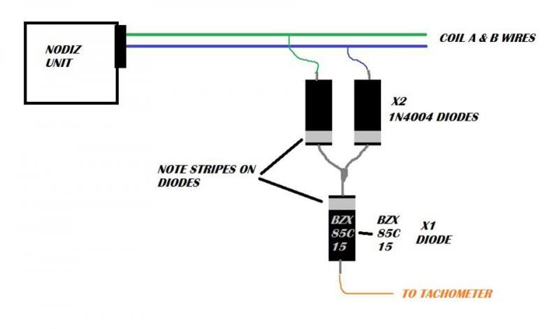
The fact it is dropping off at higher RPMs tells me that the problem may be down to the dwells of the coils overlapping (they shouldn't be at 3,000rpm, so its most likely a duty cycle requirement of the tacho) and hence its failing to register the pulses thereafter.


Another google search reveals... (I sued the keywords I gave to you of rev counter relay coil)


http://www.brumster....p?article_id=10


Give that a go - it might just work, and if it does, excellent, result!


Either way, keep me posted, we are always available on the phone - there are in fact five of us here in total - and although you may of felt rushed off, you were not, so sorry if that's what you thought.


Cheers

Matt


#13 dklawson

dklawson

    Moved Into The Garage

  • TMF+ Member
  • PipPipPipPipPipPipPipPipPipPipPip
  • 10,923 posts
  • Name: Doug
  • Location: Durham, NC - USA
  • Local Club: none

Posted 23 August 2015 - 03:22 PM

As a moderator...

Matt and Coopdog, if your discussions are going to get heated, please take them off this board.  You can use your direct emails or the PM system here on this board.


Matt, if Coopdog has your later version that has a full 12V square wave output for a tach drive, that should work perfectly with his Smiths RVC tachometer.  He should not need the diode circuit or the mosfet interface that I suggested to get a 5V signal up to 12V.


Coopdog, try a direct connection between the 12V tach output of the Nodiz to the bullet connector on your RVC tach.  You will still need power and earth for that tach but you shouldn't need anything else in the way of interface circuitry.  I bench calibrate tachs using a 12V square wave signal and can confirm this will not be a problem for the RVC.  


If the RVC tach does not respond properly with the 12V square wave, test the tach on another car to confirm it works correctly.  Once you know the tach works correctly, accept Matt's offer to inspect the Nodiz unit you have to confirm that the ignition system and its tach output are working properly.


When a solution is found, please post your findings here so they will benefit others.


#14 motorsportelectronics

motorsportelectronics

    Stage One Kit Fitted

  • Traders
  • PipPipPip
  • 54 posts

Posted 24 August 2015 - 03:09 PM

I'm here to help - no temperature rise intended :)


#15 coopdog

coopdog

    Up Into Fourth

  • TMF+ Member
  • PipPipPipPipPipPipPipPipPip
  • 4,506 posts
  • Location: South Wales

Posted 27 August 2015 - 08:00 AM

I'm here to help - no temperature rise intended :)


I'm not sure if the nodiz has a direct output for the rev counter I'm sure only the older ones have it?


1 user(s) are reading this topic

0 members, 1 guests, 0 anonymous users