Jump to content


Photo
- - - - -

How Best To Wire Up Aux Gauges...


  • Please log in to reply
11 replies to this topic

#1 minisilverbullet

minisilverbullet

    Up Into Fourth

  • TMF+ Member
  • PipPipPipPipPipPipPipPipPip
  • 3,799 posts
  • Name: Craig
  • Location: Sweden

Posted 07 March 2015 - 07:06 PM

I have three smiths gauges, A clock, oil pressure and voltmeter


All three have lamps, which need to be ignition live


Obviously the clock needs a constant live and the voltmeter will need an ignition live.


I now i need to locate, firstly a 12v feed. I have a a heated front screen, where i have taken a live feed from the starter using a 84/03 6mm wire (so fairly thick). could I use this for my live feed for the clock?


I thought I could wire these gauges up using a relay and take the ignition trigger from the, say the radio and then use the same live feed as above?


In terms of the practical side: I will have 4 separate wires (3 for the bulbs and 1 for the voltmeter) which will need to be ignition live. how do i do this? can I add them all to the same spade terminal for the relay? 


Obviously, given the above wiring isn't my strong point, so any comments welcome. 


#2 minisilverbullet

minisilverbullet

    Up Into Fourth

  • TMF+ Member
  • PipPipPipPipPipPipPipPipPip
  • 3,799 posts
  • Name: Craig
  • Location: Sweden

Posted 07 March 2015 - 07:21 PM

I should have added that since the the car is "factory" wired for daylight running, i didn't see any point in complicating things by using a side light, dash illumination feed for the bulbs in the gauges. 


#3 Tamworthbay

Tamworthbay

    Crazy About Mini's

  • Members
  • PipPipPipPipPipPipPipPipPipPip
  • 7,025 posts
  • Name: Clive
  • Location: Tamworth
  • Local Club: A5 minis

Posted 07 March 2015 - 07:23 PM

When I fitted the ones in my last mini I made up a small loom to feed them all and made it detachable from the main loom. It makes for a minimum of interference with the main loom and also means you can move them out of way easier if you need to at any point.

#4 dklawson

dklawson

    Moved Into The Garage

  • TMF+ Member
  • PipPipPipPipPipPipPipPipPipPipPip
  • 10,923 posts
  • Name: Doug
  • Location: Durham, NC - USA
  • Local Club: none

Posted 07 March 2015 - 07:34 PM

Smiths "electrical" gauges require 10V, not 12V.  Search this forum for the words "voltage stabilizer" and you will find a lot of information.  You can buy modern versions of the voltage stabilizer off eBay to power you new gauges.  Do not power your new gauges with full 12V.  They will read too high and will have a shortened life.


That said, the only gauge you mentioned that may need the stabilizer is oil pressure IF it is an electrical oil pressure gauge.  If it is mechanical, ignore the comments above and below about the stabilizer.


The stabilizer will need switched, fused power (dark green wires in the loom).

The stabilizer must also have an earth connection to its case.


The output from the stabilizer goes to any electric gauges (not the clock, not the volt meter) that you are installing.  The connection from the voltage stabilizer output can be to either gauge terminal.  The remaining gauge terminal is connected to its appropriate sending unit.


For illumination, the gauge case must have an earth connection to the car chassis (black wire between case and earth).

Gauge illumination power is typically on red or red/white wires behind the dash.  Tap into this circuit so you will have the ability to control lamp brightness with the dimmer knob (if fitted).


The time clock needs to be connected to an unfused, permanently hot wire (brown wires behind the dash).  The clock may also have a separate terminal for an earth connection.


The volt meter will need an earth connection and a connection to a switched, fused 12V supply.  As with the voltage stabilizer, use a dark green wire behind the dash for the switched 12V supply.


Edited by dklawson, 07 March 2015 - 07:37 PM.


#5 minisilverbullet

minisilverbullet

    Up Into Fourth

  • TMF+ Member
  • PipPipPipPipPipPipPipPipPip
  • 3,799 posts
  • Name: Craig
  • Location: Sweden

Posted 07 March 2015 - 08:01 PM


.

yip it is a mechanical gauge. 


regarding the bulbs, they are actually separate and just "plug in" using these 

Screen%20Shot%202015-03-07%20at%2020.54.


DKLawson, I should have said the car is an SPi.


I am a bit hesitant to over load the original wiring, especially that for the illumination of the gauges, thats why i thought i should use a relay. 


#6 dklawson

dklawson

    Moved Into The Garage

  • TMF+ Member
  • PipPipPipPipPipPipPipPipPipPipPip
  • 10,923 posts
  • Name: Doug
  • Location: Durham, NC - USA
  • Local Club: none

Posted 07 March 2015 - 10:28 PM

I like the look of that bulb holder.  Does it use the "push in" type modern bulb or does it use an older style bayonet or screw base lamp?


I understand your concern about the lamps and excess current draw.  I don't have any real advice for you on how to address this.


#7 Steve220

Steve220

    Crazy About Mini's

  • TMF+ Member
  • PipPipPipPipPipPipPipPipPipPip
  • 5,044 posts
  • Location: Shropshire
  • Local Club: BMC

Posted 07 March 2015 - 11:54 PM

On the sportspack minis, the gauge lighting is taken from the same part of the loom as the lighting for the main dials and has the same amp fuse.


Hope that's of some help.


Steve


#8 nicklouse

nicklouse

    Moved Into The Garage

  • Members
  • PipPipPipPipPipPipPipPipPipPipPip
  • 18,577 posts
  • Location: Not Yorkshire
  • Local Club: Anonyme Miniholiker

Posted 08 March 2015 - 12:24 AM

I would not be worried about over loading the wiring with the lighting side. You will not. And if you are running LEDs the draw will be even less.

#9 Spider

Spider

    Moved Into The Garage

  • Admin
  • PipPipPipPipPipPipPipPipPipPipPip
  • 14,840 posts
  • Location: NSW
  • Local Club: South Australian Moke Club

Posted 08 March 2015 - 01:09 AM

Doug, respectfully mate, only the Oil Pressure Gauge - if electric - from the OPs set would need 10 Volt. The Clock is 12 Volt and the Voltmeter is direct reading. Come on mate, you're normally 120% on the ball!


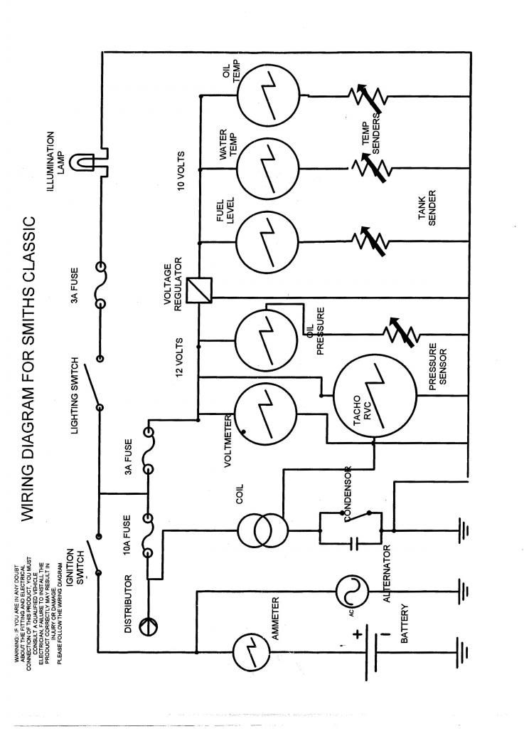
Here's a Smiths Diagram


SmithsWiringDiagram_zps42f263ed.jpg


I'd suggest any feeds that you take to the gauges be fused.


I'm not sure what model Mini you have, but if you look at the fuse box, you'll see some Purple Wires. take a feed from one of those for the Clock. Again, on the fuse box, there'll be some green wires, take a feed from one of those for the Voltmeter and if you want 'Daytime Running Lights', wire the bulbs to this connection too.


<Edit: Now I look again at the diagram, the electric OP Gauge also takes a direct 12 volt feed.>


Edited by Moke Spider, 08 March 2015 - 01:11 AM.


#10 dklawson

dklawson

    Moved Into The Garage

  • TMF+ Member
  • PipPipPipPipPipPipPipPipPipPipPip
  • 10,923 posts
  • Name: Doug
  • Location: Durham, NC - USA
  • Local Club: none

Posted 08 March 2015 - 02:55 PM

Doug, respectfully mate, ...


Chris, you missed or misread the second paragraph in my first post:

"That said, the only gauge you mentioned that may need the stabilizer is oil pressure IF it is an electrical oil pressure gauge.  If it is mechanical, ignore the comments above and below about the stabilizer."

I said that only the electric OP gauge would need the stabilizer.  In paragraphs 6 & 7 I mention 12V supply (un-switched and switched respectively) for the clock and voltmeter.


"The time clock needs to be connected to an unfused, permanently hot wire (brown wires behind the dash)."  


"The volt meter will need an earth connection and a connection to a switched, fused 12V supply. " 


I stand corrected on the oil pressure gauge.  Looking through old schematics, the earliest use of an electric OP gauge I found was for the '68 MGB.  The electric Smiths OP gauge is shown as connected to a full 12V supply.  


#11 Spider

Spider

    Moved Into The Garage

  • Admin
  • PipPipPipPipPipPipPipPipPipPipPip
  • 14,840 posts
  • Location: NSW
  • Local Club: South Australian Moke Club

Posted 08 March 2015 - 08:15 PM


Doug, respectfully mate, ...


Chris, you missed or misread the second paragraph in my first post:

"That said, the only gauge you mentioned that may need the stabilizer is oil pressure IF it is an electrical oil pressure gauge.  If it is mechanical, ignore the comments above and below about the stabilizer."

I said that only the electric OP gauge would need the stabilizer.  In paragraphs 6 & 7 I mention 12V supply (un-switched and switched respectively) for the clock and voltmeter.


"The time clock needs to be connected to an unfused, permanently hot wire (brown wires behind the dash)."  


"The volt meter will need an earth connection and a connection to a switched, fused 12V supply. " 


I stand corrected on the oil pressure gauge.  Looking through old schematics, the earliest use of an electric OP gauge I found was for the '68 MGB.  The electric Smiths OP gauge is shown as connected to a full 12V supply.  


Awesome, good to see we can keep you on your toes!


#12 minisilverbullet

minisilverbullet

    Up Into Fourth

  • TMF+ Member
  • PipPipPipPipPipPipPipPipPip
  • 3,799 posts
  • Name: Craig
  • Location: Sweden

Posted 08 March 2015 - 08:18 PM

Got it all wired up today!

Thanks guys.


1 user(s) are reading this topic

0 members, 1 guests, 0 anonymous users