Sorry about that. Thanks for posting the link Chris.


Temp Gauge Question ....
Started by
Chas campen
, Feb 28 2015 06:59 PM
28 replies to this topic
#16

dklawson
-

- TMF+ Member
-

- 10,923 posts
Moved Into The Garage
- Name: Doug
- Location: Durham, NC - USA
- Local Club: none
Posted 15 March 2015 - 09:12 PM
#17
RaulSims
-

- Noobies
-
- 92 posts
Stage One Kit Fitted
- Location: Aveiro
Posted 29 June 2015 - 11:11 AM
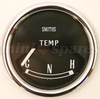
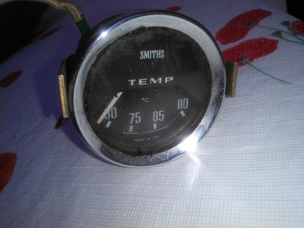
I have a question, my temperature gauge has stop working properly. I was planning to change to the one with 30 to 110ºC. Is it just a matter of connecting the same terminals than the one that i use to have (image with C and H)? Or do i have to change anything?
#18
dklawson
-
- TMF+ Member
-
- 10,923 posts
Moved Into The Garage
- Name: Doug
- Location: Durham, NC - USA
- Local Club: none
Posted 29 June 2015 - 12:08 PM
There is no simple answer to your question.
Yes, electrically all you need to do is put the replacement Smiths gauge in and move the wires from your old gauge to the new one. However, not all Smiths sending units and gauges work together accurately. When designed, the gauge will have a matching sending unit to assure accurate readings. There is nothing to say that your replacement gauge will work accurately with your existing Mini sending unit.
If you know what the replacement gauge came from (Mini, MG, Triumph, etc.) buy the matching sending unit for that vehicle and replace the sender in the Mini with the one that matches your new gauge.
#19
RaulSims
-
- Noobies
-
- 92 posts
Stage One Kit Fitted
- Location: Aveiro
Posted 29 June 2015 - 01:55 PM
There is no simple answer to your question.
Yes, electrically all you need to do is put the replacement Smiths gauge in and move the wires from your old gauge to the new one. However, not all Smiths sending units and gauges work together accurately. When designed, the gauge will have a matching sending unit to assure accurate readings. There is nothing to say that your replacement gauge will work accurately with your existing Mini sending unit.
If you know what the replacement gauge came from (Mini, MG, Triumph, etc.) buy the matching sending unit for that vehicle and replace the sender in the Mini with the one that matches your new gauge.
Thank you. I was asking because i've read that these kind of instruments "30 to 110ºC" couldn't be connected to the voltage stabilizer.
But if i can just connect the wires i will give it a try.
Thank you once again.
#20
dklawson
-
- TMF+ Member
-
- 10,923 posts
Moved Into The Garage
- Name: Doug
- Location: Durham, NC - USA
- Local Club: none
Posted 29 June 2015 - 04:25 PM
There are a handful of VERY early Smiths electrical temperature gauges that did not use the voltage stabilizer but they are not common.
Look on the back of the gauge. If there are two tiny hex nuts in addition to the electrical terminals, you do not use the stabilizer. If there are no nuts you use the stabilizer.
#21
RaulSims
-
- Noobies
-
- 92 posts
Stage One Kit Fitted
- Location: Aveiro
Posted 30 June 2015 - 11:11 AM
There are a handful of VERY early Smiths electrical temperature gauges that did not use the voltage stabilizer but they are not common.
Look on the back of the gauge. If there are two tiny hex nuts in addition to the electrical terminals, you do not use the stabilizer. If there are no nuts you use the stabilizer.
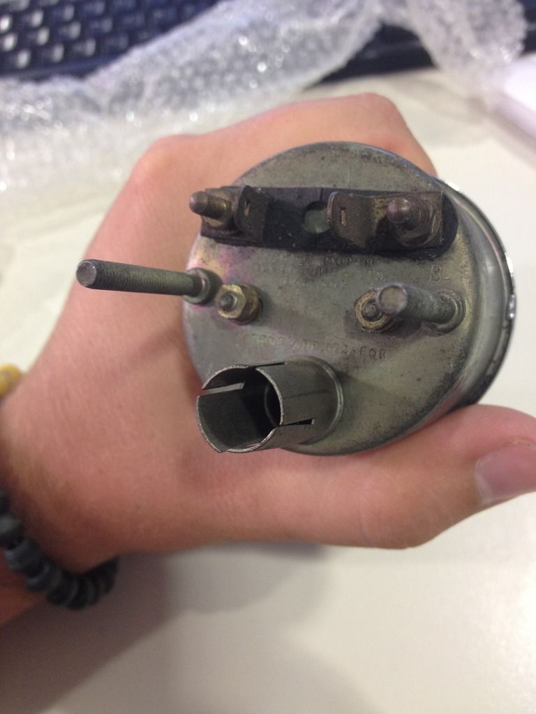
This is how the backside of the instrument looks like
#22
dklawson
-
- TMF+ Member
-
- 10,923 posts
Moved Into The Garage
- Name: Doug
- Location: Durham, NC - USA
- Local Club: none
Posted 30 June 2015 - 12:02 PM
You have a very early electrical temperature gauge. It does NOT use the stabilizer. Its accuracy will NOT be improved by attaching it to a voltage stabilizer. You are likely to have trouble finding its appropriate temperature sending unit.
Note the two small hex nuts. They are loosened and moved in slots to change the gauge calibration. Note also that one terminal is marked "B". That is for the 12V "battery" connection. The other terminal may be marked "T". The "T" designation comes from the more common use of this gauge case for fuel gauges and "T" is for "tank". Regardless of whether this gauge is for temperature or fuel, the "T" terminal goes to the sending unit.
You MAY be able to make this gauge work with more common sending units... I just don't know for sure. All I can suggest is that you wire up a bench test for the components you have and see how accurate the gauge is with the sender submerged in baths of different temperatures. Through trial and error and careful bench work you may be able to tweak the calibration of this gauge. As I mentioned earlier, the movement inside this case was more commonly used on fuel gauges. Therefore, visit the MGA Guru web site and read up on the early fuel gauge, how it operates, and how to calibrate it (link below). You could use the same calibration techniques for your temperature gauge... just remember you will need to map out the resistance range of your temperature sending unit first before starting gauge calibration. The resistance values on the MGA Guru site will be for the fuel gauge in an MGA... not temperature in a Mini.
http://mgaguru.com/m...ctric/fg_01.htm
#23
RaulSims
-
- Noobies
-
- 92 posts
Stage One Kit Fitted
- Location: Aveiro
Posted 30 June 2015 - 01:42 PM
You have a very early electrical temperature gauge. It does NOT use the stabilizer. Its accuracy will NOT be improved by attaching it to a voltage stabilizer. You are likely to have trouble finding its appropriate temperature sending unit.
Note the two small hex nuts. They are loosened and moved in slots to change the gauge calibration. Note also that one terminal is marked "B". That is for the 12V "battery" connection. The other terminal may be marked "T". The "T" designation comes from the more common use of this gauge case for fuel gauges and "T" is for "tank". Regardless of whether this gauge is for temperature or fuel, the "T" terminal goes to the sending unit.
You MAY be able to make this gauge work with more common sending units... I just don't know for sure. All I can suggest is that you wire up a bench test for the components you have and see how accurate the gauge is with the sender submerged in baths of different temperatures. Through trial and error and careful bench work you may be able to tweak the calibration of this gauge. As I mentioned earlier, the movement inside this case was more commonly used on fuel gauges. Therefore, visit the MGA Guru web site and read up on the early fuel gauge, how it operates, and how to calibrate it (link below). You could use the same calibration techniques for your temperature gauge... just remember you will need to map out the resistance range of your temperature sending unit first before starting gauge calibration. The resistance values on the MGA Guru site will be for the fuel gauge in an MGA... not temperature in a Mini.
Thank you very much again for the help. I will try to return the instrument. I have a 76 mini so i don't need this kind of trouble to use a less accurate instrument.
Thank you once again.
#24
dklawson
-
- TMF+ Member
-
- 10,923 posts
Moved Into The Garage
- Name: Doug
- Location: Durham, NC - USA
- Local Club: none
Posted 30 June 2015 - 02:47 PM
You have a rare gauge. You may want to see if someone on one of the Mk1 related Mini boards wants it. You may be able to sell it for more than you paid for it.
#25
RaulSims
-
- Noobies
-
- 92 posts
Stage One Kit Fitted
- Location: Aveiro
Posted 30 June 2015 - 04:05 PM
You have a rare gauge. You may want to see if someone on one of the Mk1 related Mini boards wants it. You may be able to sell it for more than you paid for it.
What kind of value are we talking about? Can you give me the estimated value?
A quick question, what could happen if i connect this instrument to the voltage stabilizer?
Regards!
#26
dklawson
-
- TMF+ Member
-
- 10,923 posts
Moved Into The Garage
- Name: Doug
- Location: Durham, NC - USA
- Local Club: none
Posted 30 June 2015 - 04:19 PM
What kind of value are we talking about? Can you give me the estimated value?
A quick question, what could happen if i connect this instrument to the voltage stabilizer?
I cannot estimate a price for you. I am sure you and I are on different continents.
Sorry, techo-babble follows to answer your question about the voltage stabilizer.
The job of the voltage stabilizer is to provide reduced voltage to the later bimetallic gauges (post 1964). The original Smiths voltage stabilizers were electromechanical. They have a resistance heating wire inside which is wrapped around a bimetallic strip with electrical contacts on the end. When the strip heats, the strip bends, and the contacts open. This stops current flow, and the system cools down again. When it cools enough, the points close and current starts flowing again. This opening and closing happens anywhere from several times a second to over several seconds. The voltage output of the voltage stabilizer is an on/off pulse swinging between 0V and about 14.5V (with the engine running) to deliver an AVERAGE of 10V. The problem is... your early gauge works by magnetics, NOT bimetallic heating. The magnetic gauges respond almost immediately to current flow changes. Therefore, depending on the on/off switch rate of the voltage stabilizer you use, the early gauge's needle is going to bounce all over the place each time the stabilizer contacts open and close. In short, it's not a good idea to use the stabilizer with the early gauges. As I mentioned earlier, it does not help with accuracy. The stabilizer can make the magnetic gauge read worse.
#27
RaulSims
-
- Noobies
-
- 92 posts
Stage One Kit Fitted
- Location: Aveiro
Posted 30 June 2015 - 04:33 PM
What kind of value are we talking about? Can you give me the estimated value?
A quick question, what could happen if i connect this instrument to the voltage stabilizer?
I cannot estimate a price for you. I am sure you and I are on different continents.
Sorry, techo-babble follows to answer your question about the voltage stabilizer.
The job of the voltage stabilizer is to provide reduced voltage to the later bimetallic gauges (post 1964). The original Smiths voltage stabilizers were electromechanical. They have a resistance heating wire inside which is wrapped around a bimetallic strip with electrical contacts on the end. When the strip heats, the strip bends, and the contacts open. This stops current flow, and the system cools down again. When it cools enough, the points close and current starts flowing again. This opening and closing happens anywhere from several times a second to over several seconds. The voltage output of the voltage stabilizer is an on/off pulse swinging between 0V and about 14.5V (with the engine running) to deliver an AVERAGE of 10V. The problem is... your early gauge works by magnetics, NOT bimetallic heating. The magnetic gauges respond almost immediately to current flow changes. Therefore, depending on the on/off switch rate of the voltage stabilizer you use, the early gauge's needle is going to bounce all over the place each time the stabilizer contacts open and close. In short, it's not a good idea to use the stabilizer with the early gauges. As I mentioned earlier, it does not help with accuracy. The stabilizer can make the magnetic gauge read worse.
Thanks once again. That has been very helpful.
#28
JonnyAlpha
-

- Members
-
- 2,748 posts
Up Into Fourth
- Location: North Devon
- Local Club: Exmoor Minis
Posted 08 June 2023 - 07:39 PM
Sorry posted in the wrong thread 
Edited by JonnyAlpha, 08 June 2023 - 07:43 PM.
#29
JonnyAlpha
-
- Members
-
- 2,748 posts
Up Into Fourth
- Location: North Devon
- Local Club: Exmoor Minis
Posted 08 June 2023 - 07:42 PM
So following up on this, the new 74 degree thermostat turned up and I have dug out the mechanical gauge that I bought a long while ago when I picked up a handful of other gauges.
I installed the mechanical gauge in the dash and took the temp new sender out of the cylinder head, but left it connected to the loom. I added an earth and then popped them both into a tub of hot water.

This was the instrument cluster gauge readout:

And this was the readout from the mechanical gauge:

Does that look correct, meaning that just under N is about 65 degrees?
What are the C N and H temps?
I then drained off some coolant, looks cruddy already, even though the block and head were extensively cleaned, looks like I'll be draining and refilling it shortly.

I then undid the thermostat housing to remove change the thermostat.
Heres the 82 degree thermostat, just under my thumb the brass circle is a loose rivet that partially fills a hole to allow water through.


Heres the 74 degree thermostat, before I drilled a 3mm hole in it (as it never had one).

Once installed I went to fit the mechanical gauge sender unit:

Damm thing didn't fit:

So, I've been told to get an adaptor (or two), to fit into the hole giving more depth.
Problem is I am getting conflicting advice on what the thread is, so, what is the thread 5/8" UNF or 5/8" NPT or 5/8" BSPT or 5/8" BSPP?
https://www.holden.c...ender_070_017?s
This is the Mini Spares version, looks identical, but doesn't give any threads?
http://www.minispare...lassic/TE5.aspx
But what if I want to run both a mechanical sender / gauge and the stock send and gauge, so that I can have all gauges working?
Could I fit one in the thermostat housing, I understand that this would not read straight away, as I don't want to fits a sandwich plate.


1 user(s) are reading this topic
0 members, 1 guests, 0 anonymous users


