Cooper Mpi Restoration - My Second Mini Project
#121

Posted 21 November 2015 - 11:02 PM
Here is a demo video. The input pulses is set at 60mph for calibration.
https://youtu.be/DqJVzAVIFO4
#123

Posted 22 November 2015 - 09:35 PM
Yes I would do myself machining on CNC I work in machining and cutting tools.
Looks good. Very similar to the West garage kit I purchased.
Will you be machining it yourself?
You will get better clearance between the engine block and rear of the front subframe if your bearing blocks are round or have round edges. Mine are very tight tolernace and will need trimming down to allow better positioning.
You will also need an output covers for the output shafts to fit into. My kit uses standard mini output covers. Others use custom machined.
I can post close-up pics and measurements if you require them. I can't for a few weeks though.
#124

Posted 23 November 2015 - 07:40 PM
Yes indeed for media that I will work, I study currently functional assembly of the unit and especially the étanchieté and lubrication.
If not for the support plate gimbals, I will either use those then rework origin or sockets by using the original seal and bronze bearing.
I do not mind a maximum of photos of your project since we are on the same type of preparation.
I use a 1300 suzuki hayabusa engine so instead in the engine compartment will be limited, I have to do a test this weekend. If instead it will be a lack of front flip clubman.
Edited by kevtm49, 23 November 2015 - 07:40 PM.
#125

Posted 15 February 2016 - 04:27 PM
I can't believe it's 3 months since I last updated!
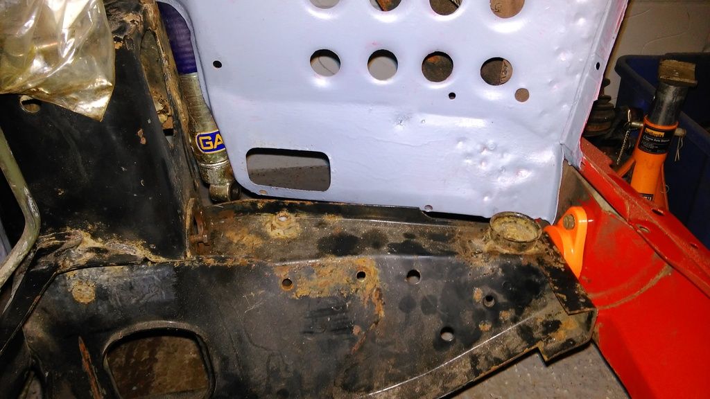
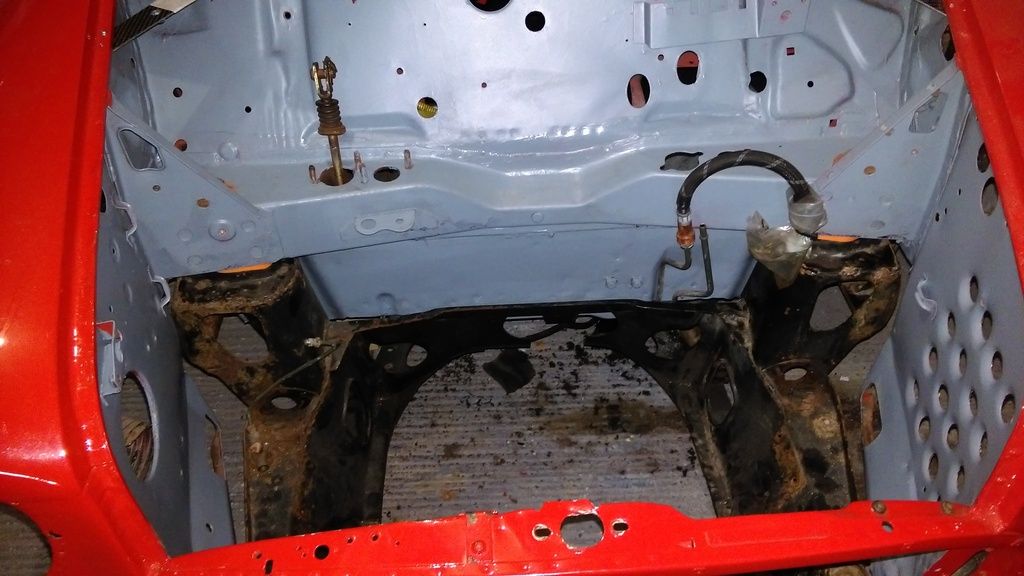
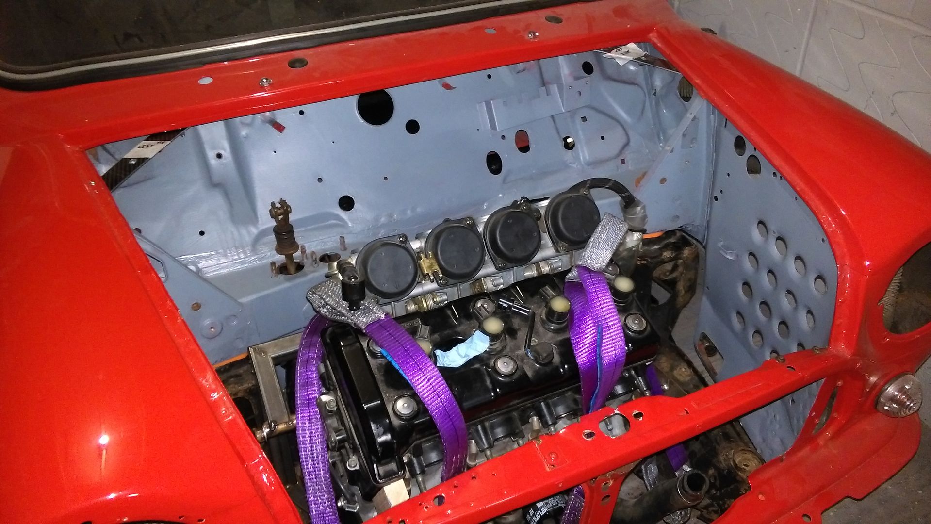
I haven't achieved lots in the last few months but some progress has been made. I've mainly concentrated my efforts on sorting the engine bay out. It's now full stripped back and has been re-painted in anti-rust primer. I've decided on a colour and will post a picture up once it's painted.
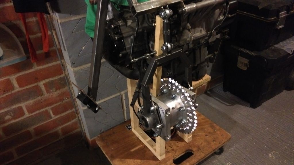
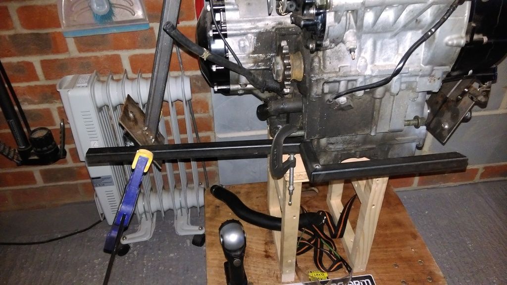
Over the weekend I managed to get some motivation to build an engine stand attached to wheels so I can lift the engine to a better working height and to make it easier to move it around. I also dry assembled the chain drive diff using a standard diff that'll do the job whilst I finish fabricating. The final build will use a cross-pin diff.
I placed an order today for some bigger heavier duty rose joints plus some u-shaped mounting brackets. Once these arrive I will get cracking on the diff hanger mounting.
Engine cradle to-do list;
1. Diff hanger mounting
2. Diff hanger tension system
3. Trial fit engine, cradle in car before proceeding
4. Lower engine mount
5. Electric reverse motor mount
6. Seam weld all joints.
#126

Posted 20 February 2016 - 05:41 PM
A much overdue update on progress. Sat 20/02/2016
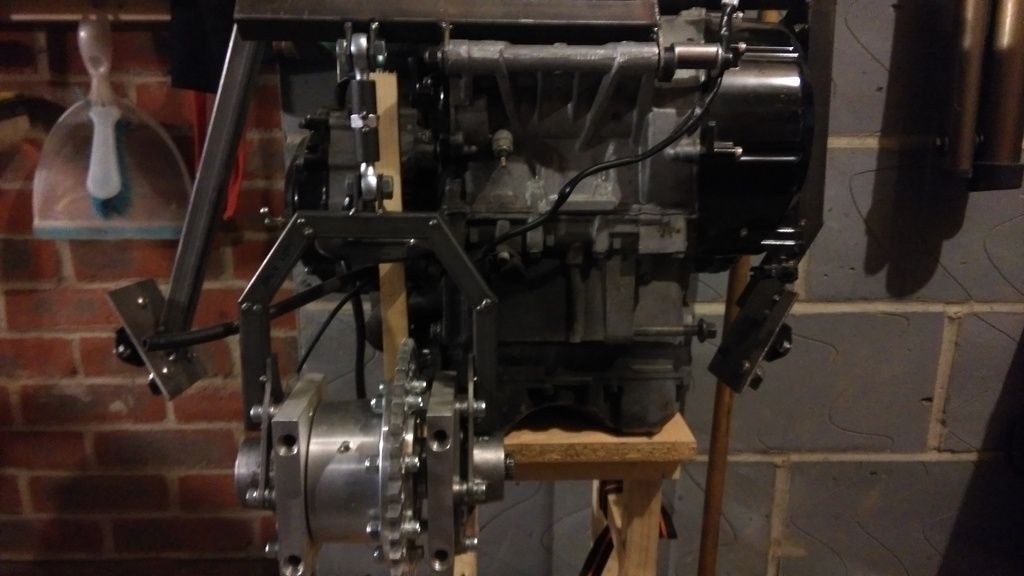
Last weekend I made up a wooden frame to lift the engine off the floor and to make it easier to move. This has a huge impact on motivation because I can just walk in the garage now and the engine is ready to work on. Fast forward a week and few eBay deliveries later and I have managed to turn quite a big corner with the cradle fabrication.
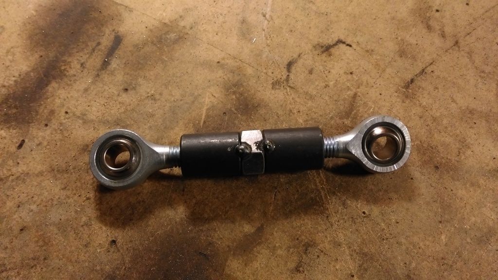
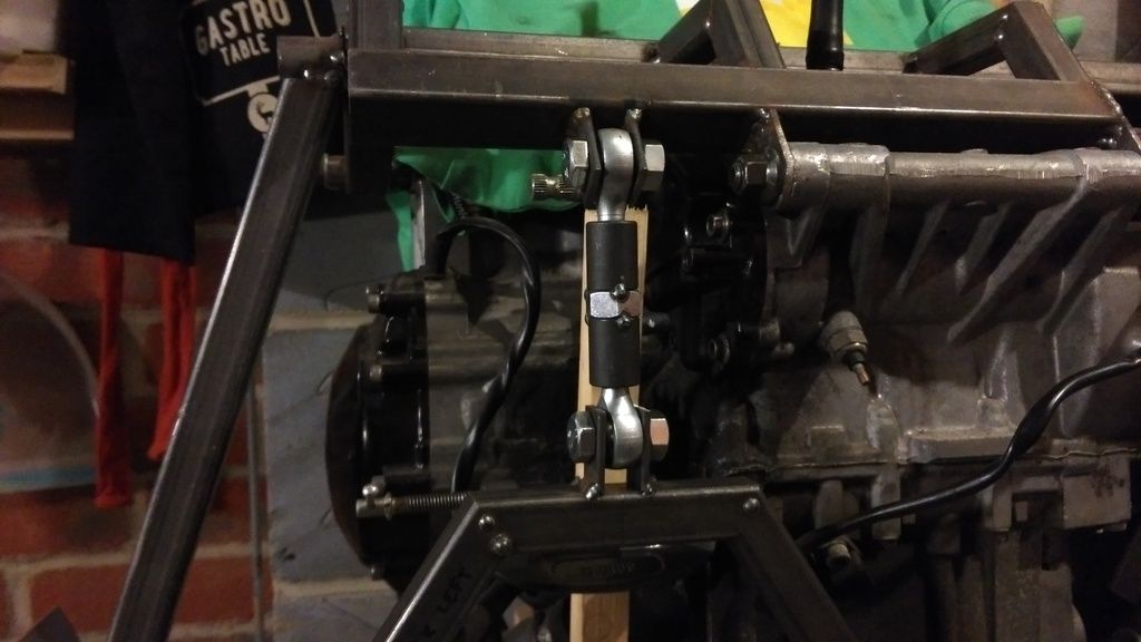
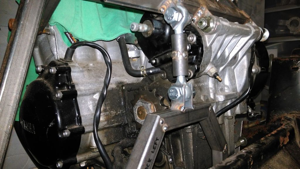
I tackled the upper diff hanger mounting this morning. I started out with some weldable threaded inserts and a large nut that I thought would help with adjustment. It turns out that it made the overall length too long so I altered it (later pics further down)
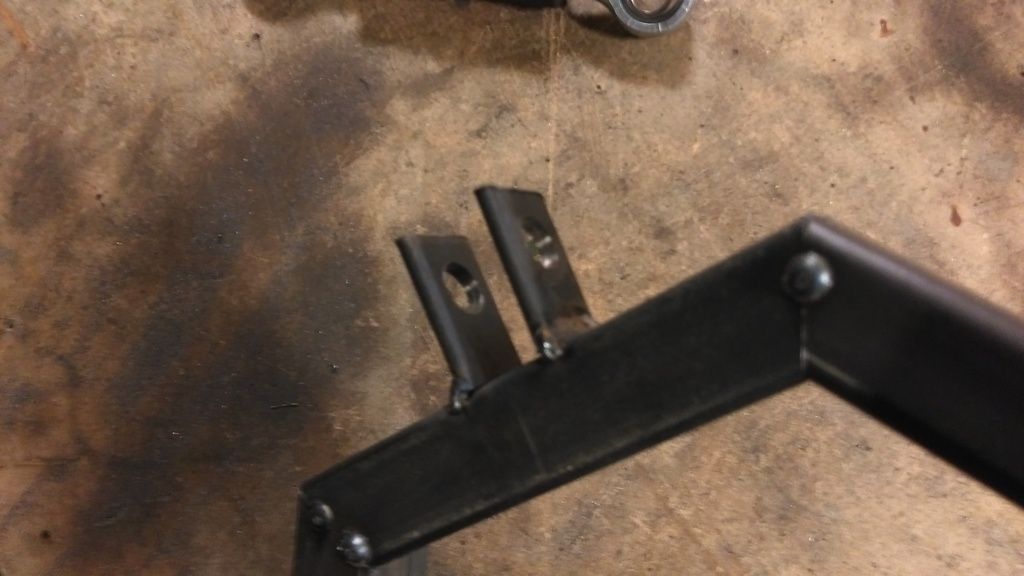
For the mounting tabs I used some 2mm flat bar that I cut into 30mm lengths and drilled 10mm holes in using a drill press. I plan to beef these up a bit once I am happy with the alignment of everything.
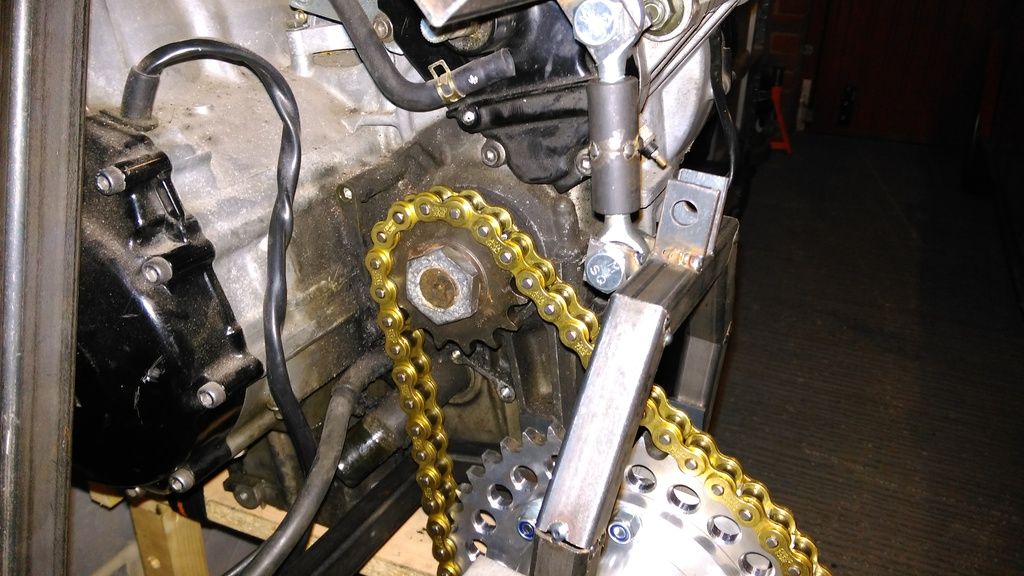
To make sure the rear sprocket lined up with the front sprocket I clamped a straight piece of wood to the front sprocket and used it as a guide. The rose joints have a bit of movement in them so I can account for slight mis-alignment. The bottom mounts will hold everything square when I get onto making them.
As stated above, the overall length of the link bar was too long so I ground the welds down and removed the nut then welded it back up. As with everything on the build so far, I have just tack welded so I can fairly easily make adjustments. I plan to install it all in the car before committing to fully seam welding.
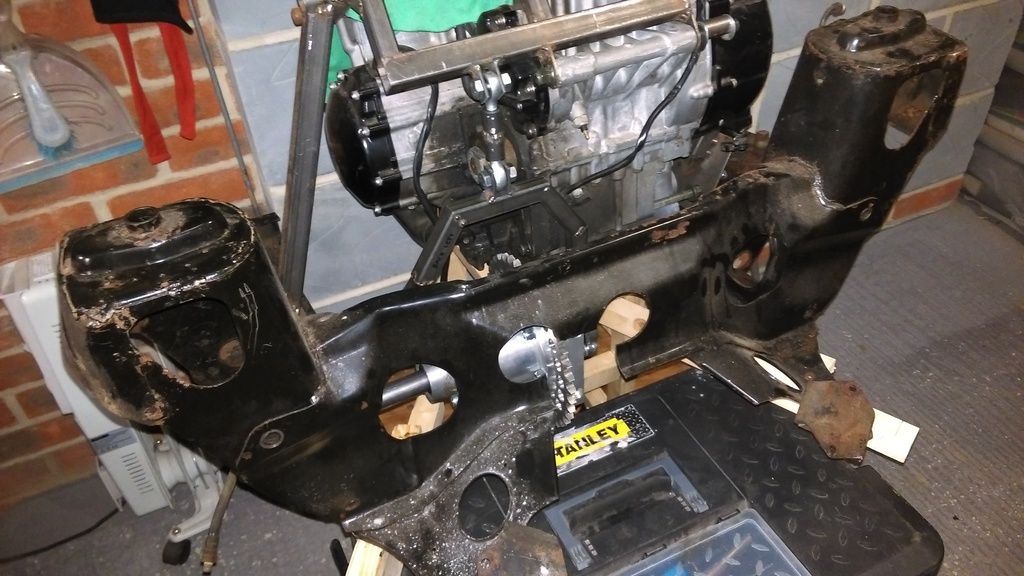
Next job was offering up the subframe to check everything fits. The cut-out on the rear of the subframe is temporary and will be strengthened up with a new plate and tighter opening to the chain now that I know it's final position.
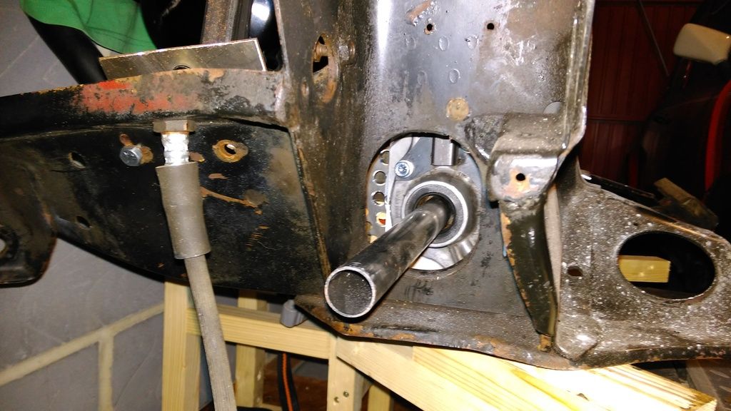
I used some round steel tube to check drive-shaft alignment. It's sitting slightly lower than required so I will need to trim the diff hanger by approx 10-15mm to lift the whole thing higher. Shortening the rose joint link isn't an option.
Not bad for 3 hours work. Sadly I ran out of welding wire on my last tack and I think the gas is about gone so it's off to get some more before I can continue.
Edited by LukeH, 20 February 2016 - 05:45 PM.
#127

Posted 23 February 2016 - 05:00 PM
Some new pollyflex subframe pear mounts arrived today so I will be able to get the subframe attached to the car again ready for an engine trial fit before I continue any further with the cradle fabrication. I'm at a point where I can still make adjustments fairly easily. The next planned phase will commit the cradle to its final position so I want to be certain its correct.
I'm also going to play around with the brake servo position once the engine is installed. I've seen a vtec install with the servo angled towards the inner wing which should give me enough clearance for the engine throttle bodies/air filter. I want to get all the metal fab and engine bay mods complete so I can give it a coat of paint after the engine comes out again.
#128

Posted 25 February 2016 - 01:21 PM
Spent some more money (all I seem to do on this project) and now have;
- Bike chain
- Chain splitter
- Welding wire
- Welding gas
Should be able to make some more progress this weekend.
#129

Posted 27 February 2016 - 04:59 PM
Today was a massive step foward with the project. It was the first time I have trial fitted the new engine cradle in the car and I was a bit nervous that my measurements would be out and I'd have to make alterations to the frame or worse, start again for the second time.
I fitted the subframe using the new polly bushes I purchased.
The engine bay is also looking a lot better since I stripped it down and gave it a coat of primer. I will be painting it soon once I have finished all the fabrication rerquired. More on that below.
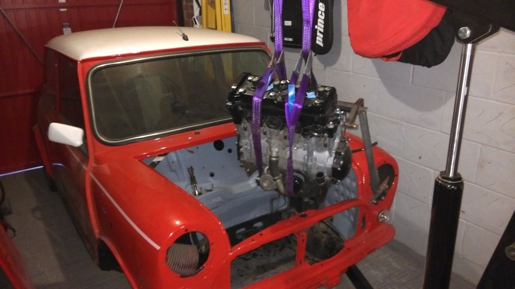
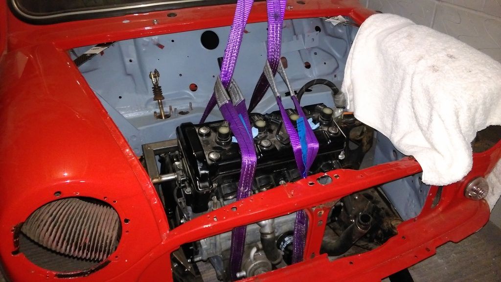
Next job was lowering the engine into place using my crane. I had to be careful not to scratch the paint so I used a towel to cover the nearside wing.
It fits! lined up exactly where I expected it to. The subframe mounts lined up perfectly with the bolt holes and all looked good.
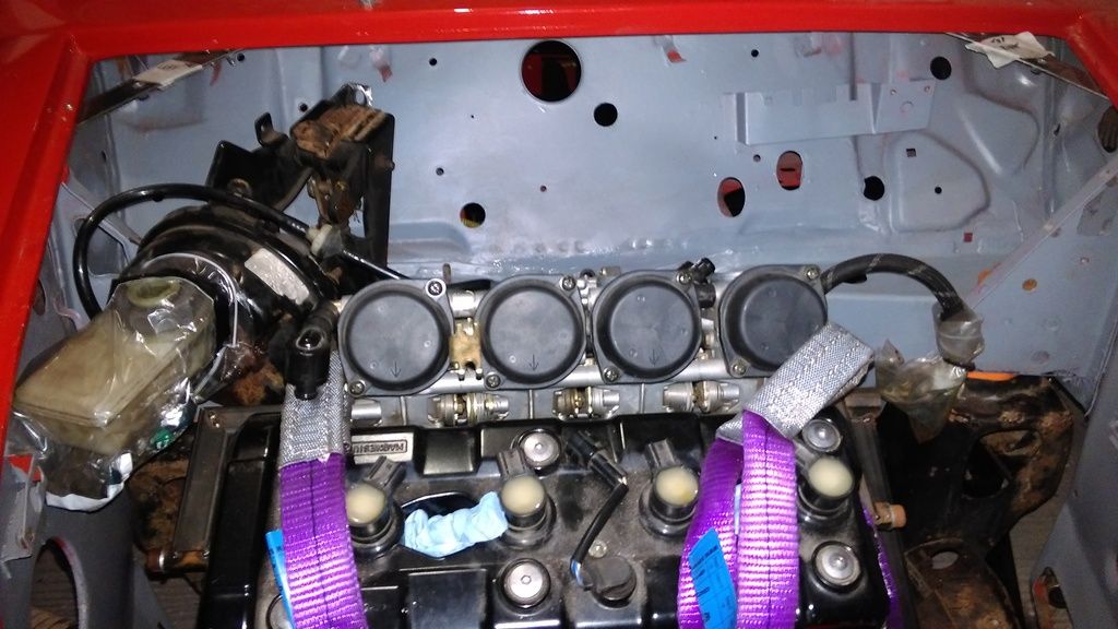
I placed the throttle bodies onto the engine and tried the bonnet - all good!
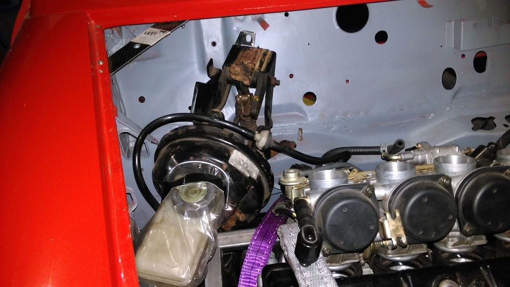
So with the engine sitting where it should be and the throttle bodies attached, I decided to tackle one of the things that has been bugging me for quite some time but I couldn't do anything about it without the engine fitted. The brake servo.
The MOT regulations have changed recently stating that a car factory fitted with a servo should have one in order to pass the MOT. Some might disagree and say I'd get away with not havinig one but I just want to reduce the number of things to be pulled up on when it comes to an MOT. It's bad enough sticking a bike engine in a mini without giving the tester and possibly police something to pick fault with.
My solution, angle the servo off towards the inner wing.
I had to trim some of the triangle gusset that goes between inner wing and bulkhead. I also had to cut to of the mounting studs off just retaining the right-hand side stud which is also the left hand stud for the clutch master cylinder. I'll be welding new studs back on in the nex position later.
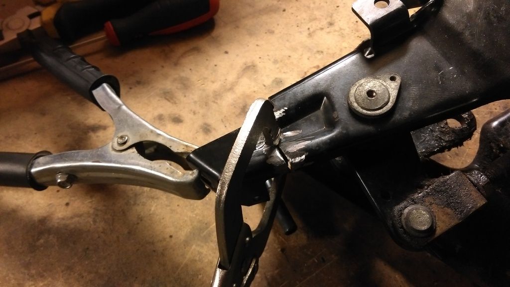
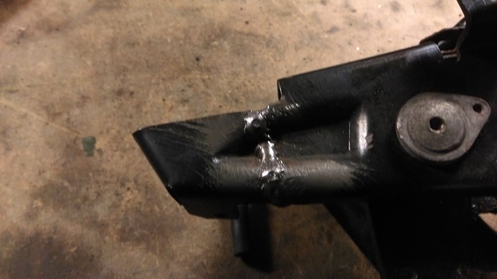
With the new servo position determined I had to shorten the rear of the bracket so that the rear bolt hole sat flush with the firewal. I cut it off with an angle grinder and removed a further 3mm. About 5mm in total removed. Then I welded it up in it new, shorter position.
Result. One offset mounted brake servo. The pedal upright will need to be modified so the clevis fork is at the correct angle. I will probably cut it off, tap a thread on the shaft and fit a new clevis fork with a thread and use a locknut to secure the position.
Edited by LukeH, 27 February 2016 - 05:05 PM.
#130

Posted 27 February 2016 - 07:29 PM
Love the smiths clock too!
#131

Posted 28 February 2016 - 09:57 PM
It was tricky to get all the angles accurate as whilist ensuring it lined up with the engine mount holes.
Chain clearance is good and bottom rad hose is clear.
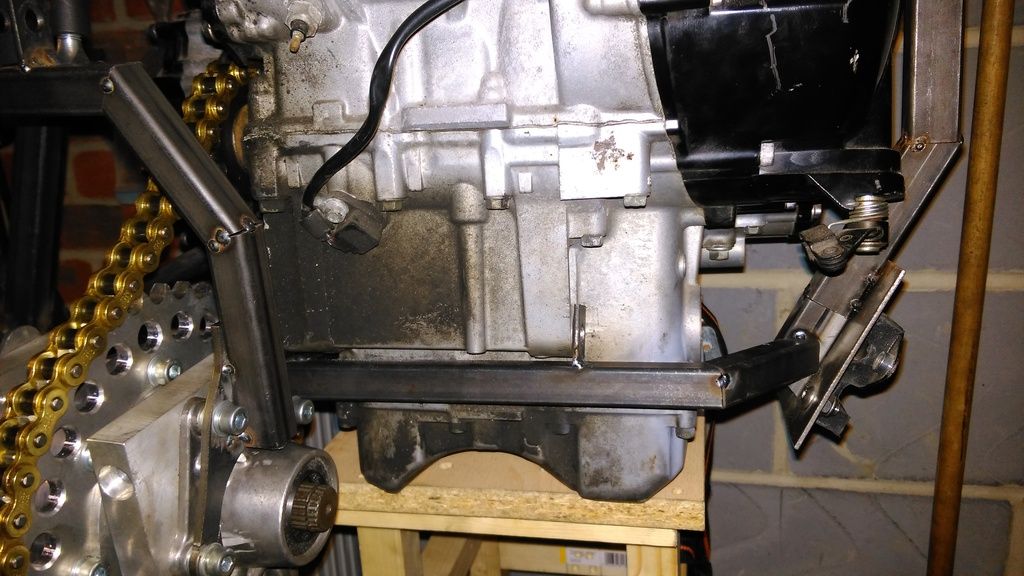
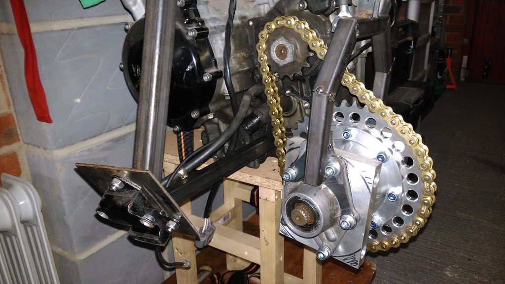
I also changed the diff hanger rose joint mount position which works much better. The old one will be cut off once I'm happy with everything.
Edited by LukeH, 28 February 2016 - 09:59 PM.
#133

Posted 29 February 2016 - 12:34 PM
Hi
I will be attaching it exactly as you have indicated using adjustable rose-jointed links bars. This coupled with the top mount will allow me to fine-tune the up/down and forward/backward position.
I have purchased the rose joints and steel tube for the link bars and can get on with making them now that the lower engine mount is done.
Luke.
#134

Posted 29 February 2016 - 12:56 PM
Ok, that's what I thought.
Ae on the lynx kit I do not know how it is fixed because all the pictures I've seen I do not see that high fixation.
Continue to photos that's interesting.
#135

Posted 29 February 2016 - 01:21 PM
Ok, that's what I thought.
Ae on the lynx kit I do not know how it is fixed because all the pictures I've seen I do not see that high fixation.
Continue to photos that's interesting.
The lynx kit does have a lower mount from the frame to diff. It's difficult to see on most pictures. I don't think its a adjustable though in terms of forward backwards, it's just a fixed pivot point. Anyway, I want my frame to be unique to me. The lynx design is a good reference.
1 user(s) are reading this topic
0 members, 1 guests, 0 anonymous users


