Cooper Mpi Restoration - My Second Mini Project
#91

Posted 05 October 2015 - 10:48 AM
#92

Posted 09 October 2015 - 08:49 PM
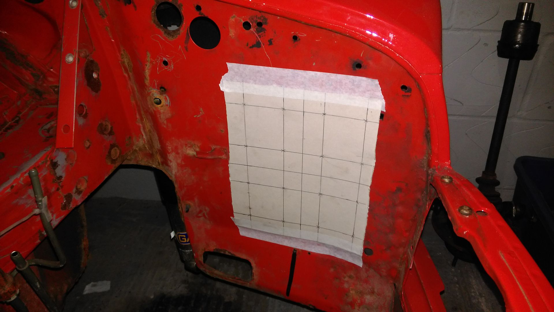
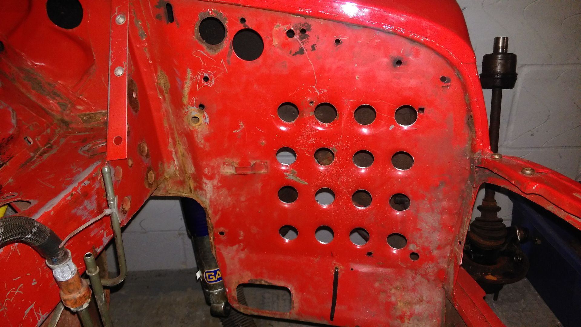
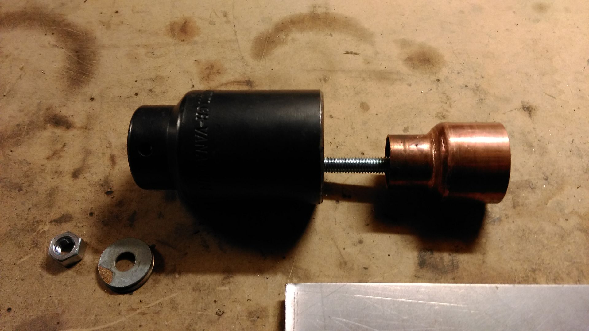
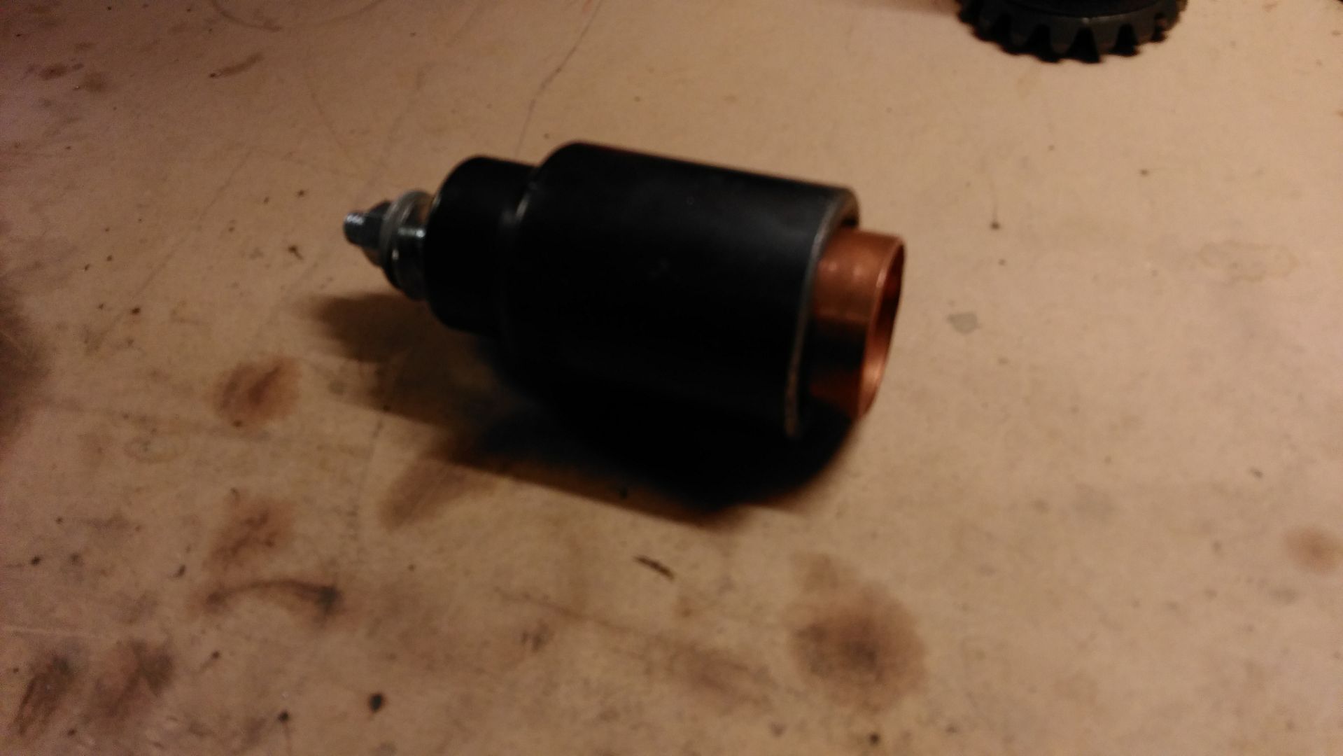
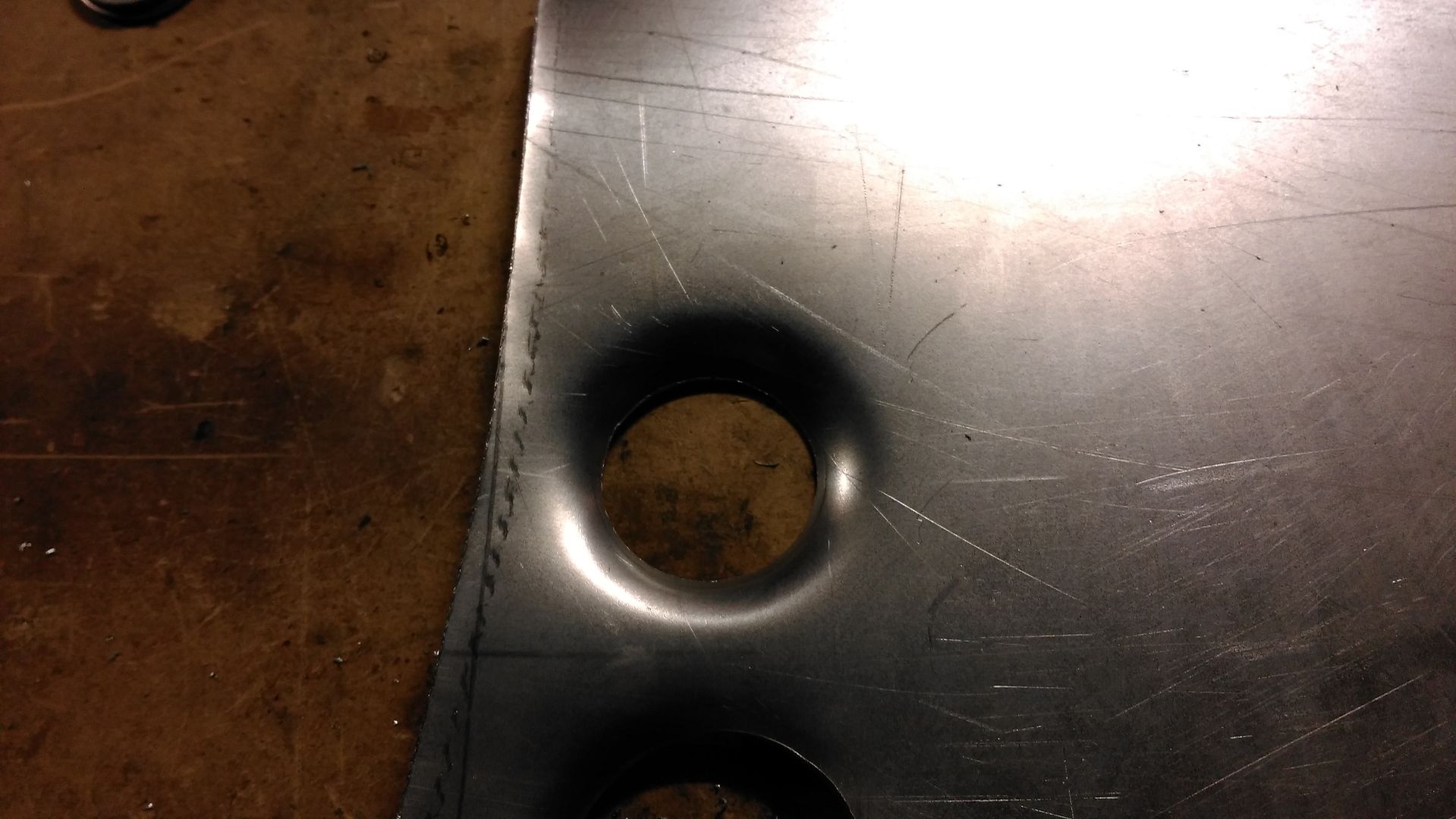
I'll be using this to put some holes in the passenger side inner wing ready for when I mount the rad.
Edited by LukeH, 12 October 2015 - 12:27 PM.
#94

Posted 10 October 2015 - 07:41 PM
#95

Posted 11 October 2015 - 03:52 PM
#96

Posted 11 October 2015 - 06:09 PM
That not the wrong wing?
No my engine is facing forward as it would in the bike so the rad goes the same side a mini rad would go.
#97

Posted 12 October 2015 - 12:31 PM

The bottom holes are toggles switches and the top are LEDs. The centre button is a push button for the bike engine statt. I plan to have the labels etched into the carbon.
Edited by LukeH, 12 October 2015 - 12:33 PM.
#98

Posted 14 October 2015 - 03:34 PM
Flappy paddles
The Klicktronic kit I picked up on eBay arrived a few days ago and quick test proved it was all in good working order. The kit I purchased came with the motorbike mounted push switches which are simple push to make switches; Green = Up, Red = Down. Now I could just install a couple of push buttons on my steering wheel or even use the horn buttons (using a replacement horn button somewhere else) to control the klicktronic system for gear changes but I much prefered the idea of some flappy paddles.
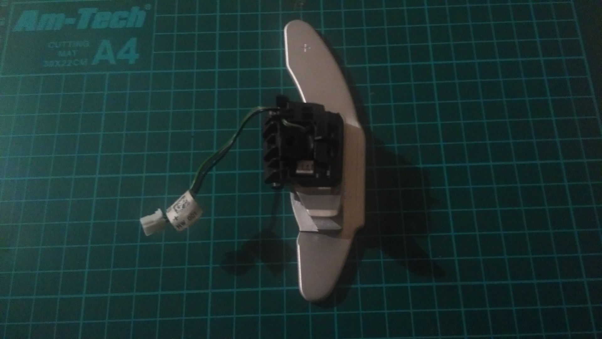
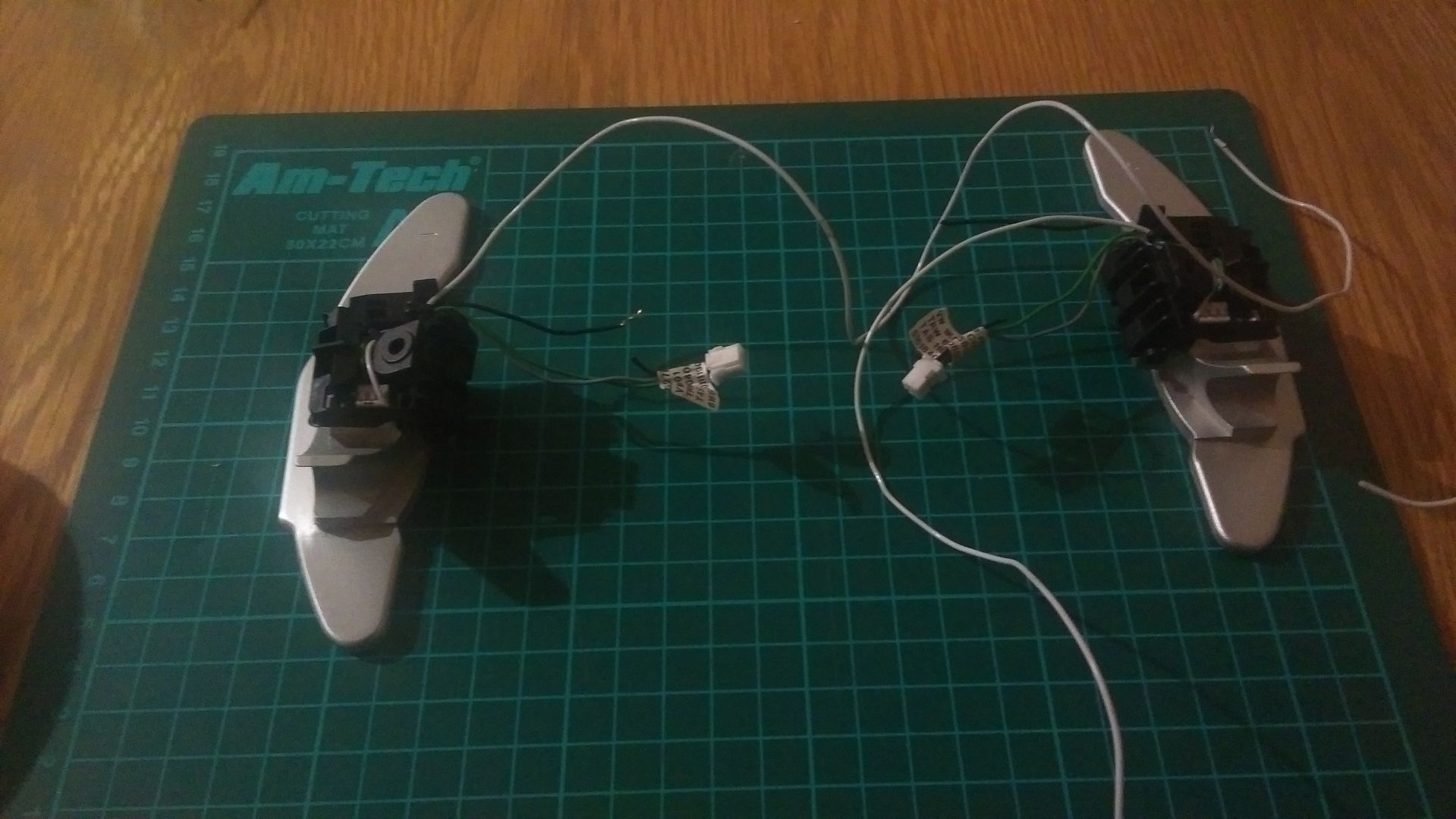
Another eBay search found these Golf R32 paddles for less than £15 delivered. I purchased a pair the other one isn't pictured.
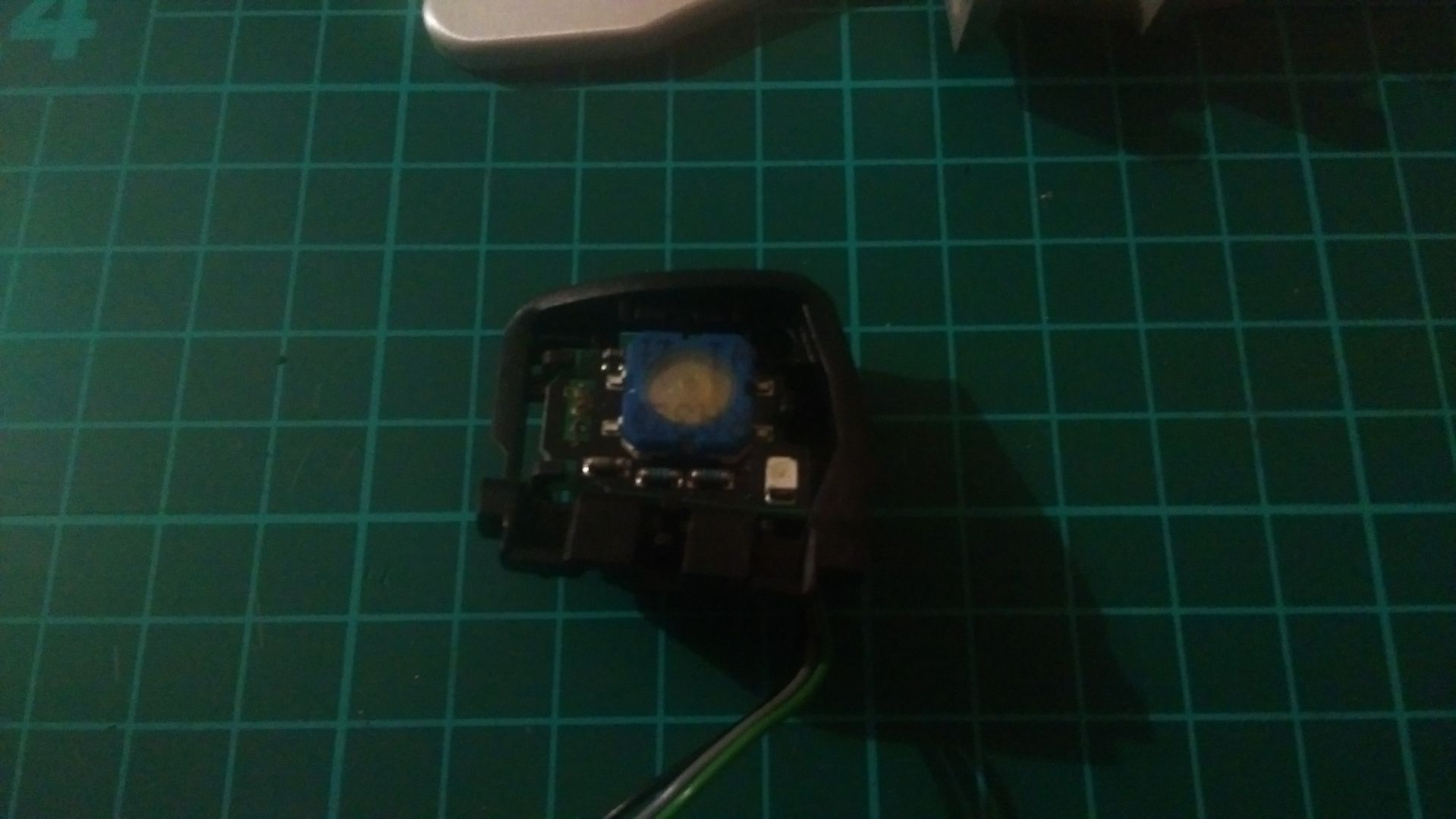
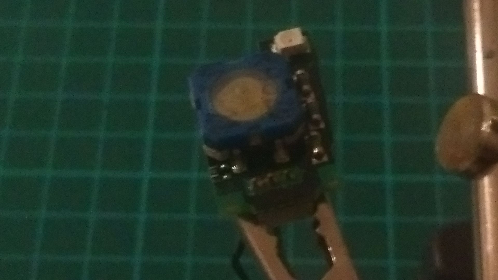
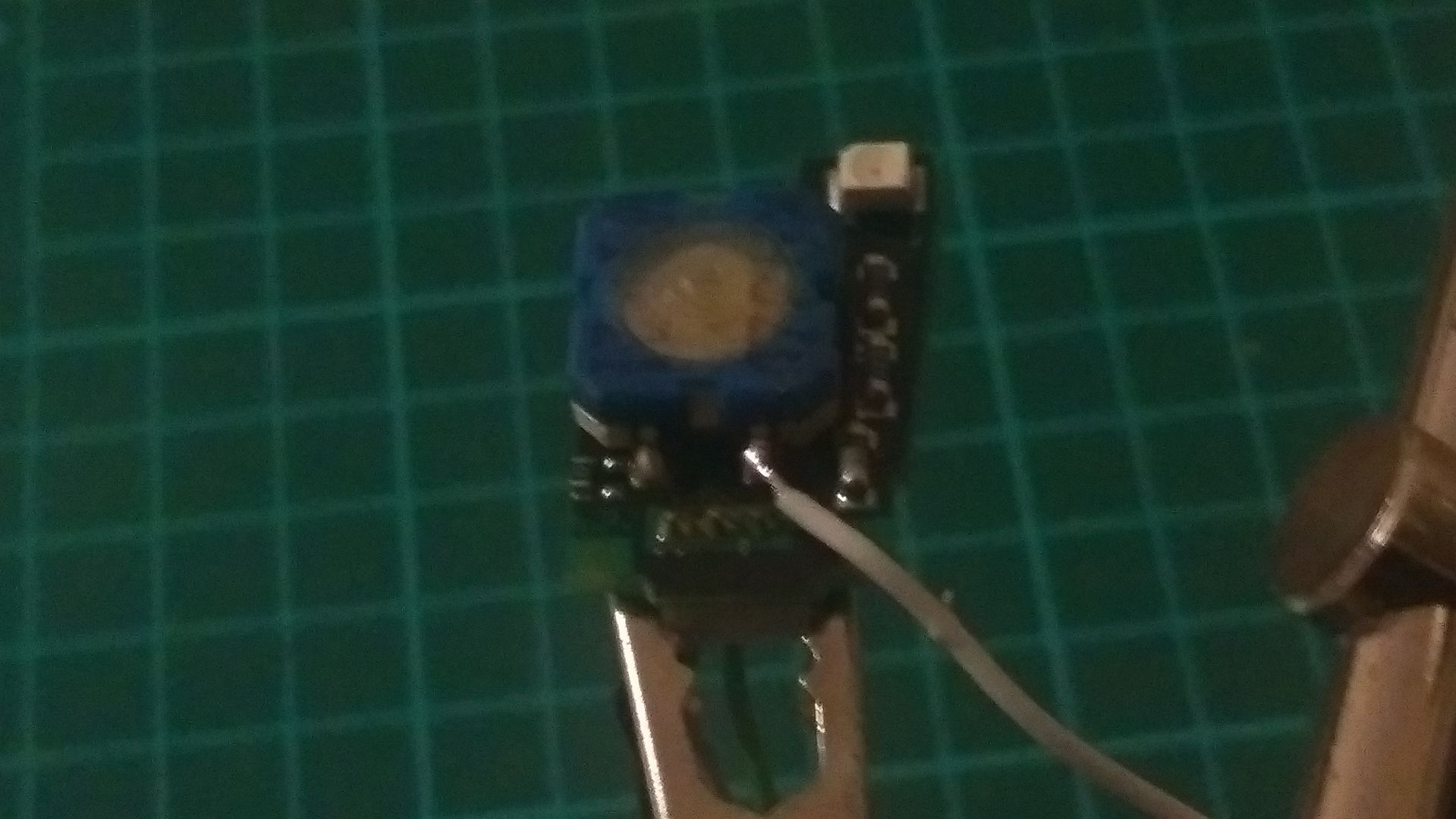
A quick inspection with a mulitmeter revealed the internal switch does not have contunity across a pair of wires which I assume is due to them using some sort of voltage drop comparison to represent a button press in the golf so I decided to take them apart and add a wire to the interal push switch.
Now when I press the paddle it simply makes a conenction on the internal switch across two pins making the black wire connected to the new white wire. I can easily hook these up to the Klicktronic control box in place of the standard push switches.
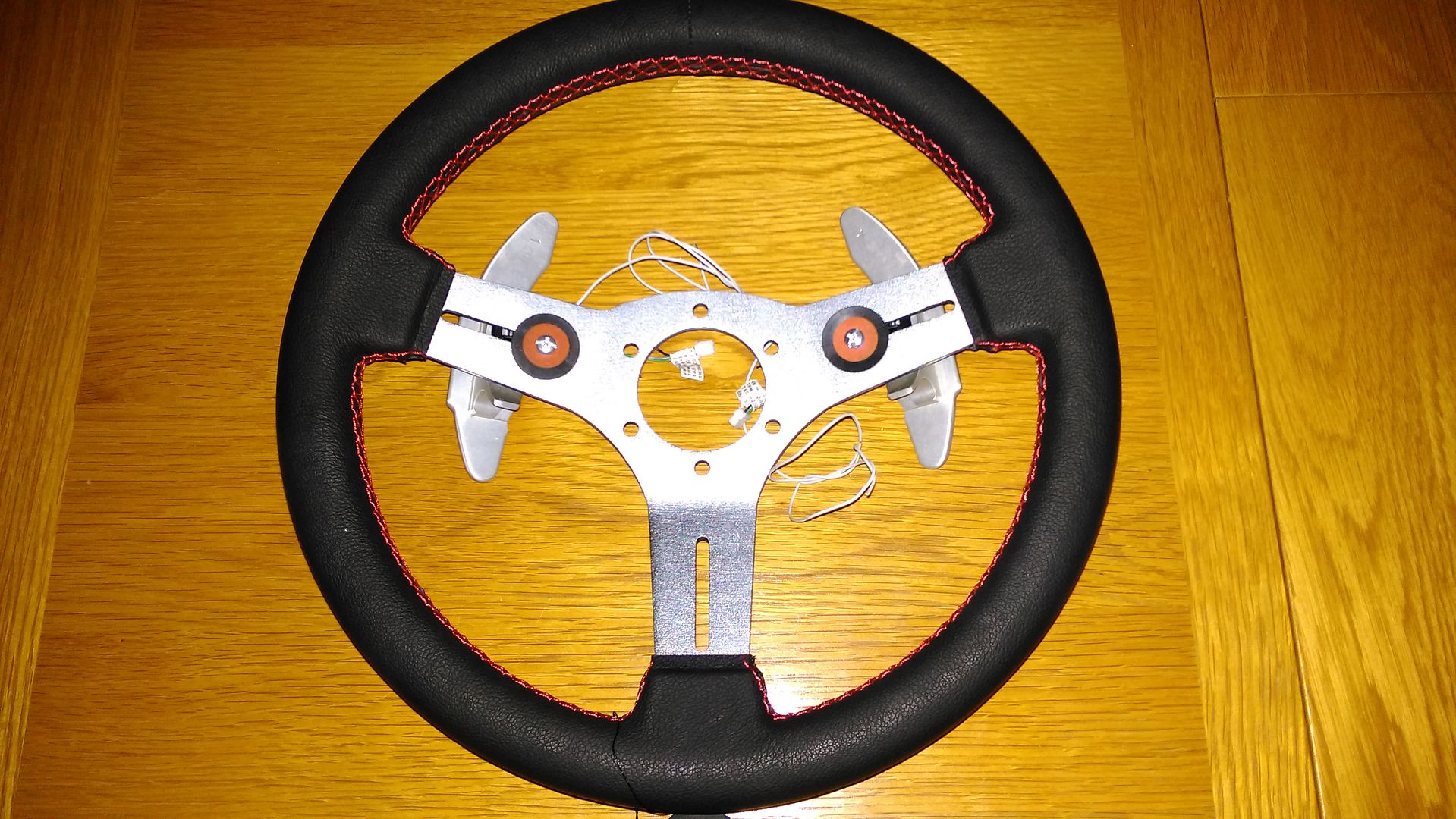
I've also made a cardboard template for a mount so these can be attached to the steering wheel by sandwiching the plate between the steering wheel and boss. I'm also hoping I can route the cables inside the wheel and make use of the spare pins on the rotary coupler as I only need three.
Edited by LukeH, 14 October 2015 - 03:40 PM.
#99

Posted 16 October 2015 - 01:24 PM
I won't be attaching them via this method when finishes but it does allow me to determine position and take measurements for the bracket I need to make.
#100

Posted 16 October 2015 - 03:17 PM
Looking like a good start. Good luck with the build.
#101

Posted 22 October 2015 - 04:31 PM
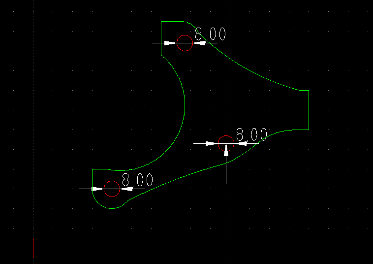
I've knocked up this CAD drawings of a bracket I will get made which will form part of the diff cradle I am fabricating. The shape is critical to get right as it will bolt on the output covers.
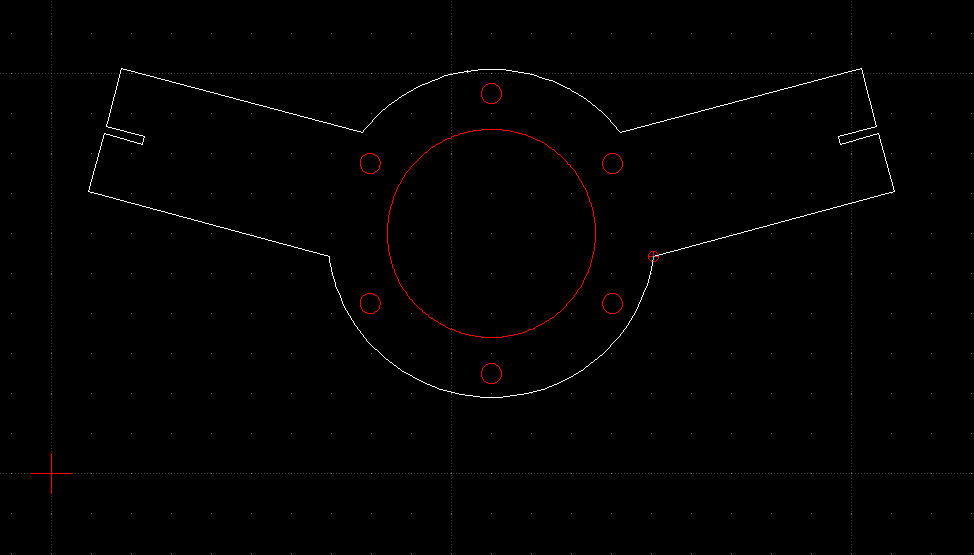
I've also drew this CAD drawing of a paddle mount for the gear shifters. I've only been using CAD a couple of weeks now so it was a bit of a challenge getting all the angles and hole alignments correct. This will be cut from 2mm steel and will be sandwiched between the steering wheel and boss. The slots at the ends are to centre the paddles and I'll drill a hole in them to pickup the paddle standard mount points. I've tested all this in cardboard first and it all lines up perfectly.
The thing that has been taking up all my spare time recently has been getting to grips with Arduino programming. It started out as a request for help in the Mini Chat section for a solution to drive a standard Smiths speedometer from a digital pulse (R1 output). I 'm now well on track to having a prototype to test as soon as a couple of components arrive. I plan to build a Arduino device that will count the R1 pulse singnal, convert to PWM to drive a DC motor that will be attached to a standard mini speedo cable which will be spun at the appropriate RPM to drive the needle and odometer. Watch this space for a demo video.....
Last, I have stumbled across OLED displays during my Arduino research and I found some code that turns an Arduino + OLED into a custom gauge, so......I now have a prototype gauge that will act as a battery charge sensor, water temp, oil pressure, oil temp (whatever I can measure essentially) Each screen can be selected from a single button to display each sensor reading. I plan to mount this in a smiths 52mm gauge to keep the stock look. I will get a video posted shortly of my working prototype
Edited by LukeH, 22 October 2015 - 04:33 PM.
#102

Posted 24 October 2015 - 04:49 PM
A video of my prototype gear position indicator that I will mount inside a smiths gauge. Well the OLED will be mounted inside the gauge and the Arduino will be in a small project case hidden somewhere.
My code is probably a little over the top but it all works as expected. I've built a start-up check that acts as a calibration. It checks if Neutral is sensed and if not it prompts to select Neutral. The display won't change until Neutral is selected but under normal circumstances I would turn the engine off in nuetral anyway. All subsequent gear changes are calcultated by simple +/- 1 from previous position. It will only allow 1-6 to be displayed to avoid incorrect gear showing if try grab 7th for example.
I'm going to work on adding a "SMITHS" startup logo which shouldn't be too much trouble.
Luke
Edited by LukeH, 24 October 2015 - 04:51 PM.
#103

Posted 24 October 2015 - 06:13 PM
#104

Posted 27 October 2015 - 04:10 PM
Another Arduino project under development. The plan is to have two Smiths gauges with OLEDs fitted in them mounted in the centre speedo binacle. One will be the gear indicator and other will be this mulit-gauge;
I've added 4 screens so far to monitor both batteries (I'm going to run a separate bike battery for the bike loom and split charge), water temp and oil pressure. I will probably add oil temp too. A single button toggles through each screen and the same button is used to dismiss the warnings but the warning isn't reset until the reading falls below the safe level. I might develop further so the warning is displayed again after a delay.
Credit goes to this guy for the intial code I've based mine on - http://xisantix.weeb...om/e-gauge.html
The Arduino board I am developing on is an Uno which is quite small but still probably too big to mount sensibly in the min, especially if I need three so I've ordered a couple of Nano to try out. At £3.50 each it's too cheap not to try them.
Edited by LukeH, 27 October 2015 - 04:14 PM.
#105

Posted 03 November 2015 - 10:06 AM
Bit of a disaster last night. I realised my engine is sitting too low in the subframe resulting in the front sprocket being too close to the diff chain ring and if I lower the diff it will be sitting too close to the ground for comfort so........it looks like I need to build a MK2 engine cradle.
All is not lost as I can reuse some of the parts I've made and I actually want to improve a few things so this is just a good opportunity to do so. I'll need to build some sort of jig so I can make sure the new cradle is square and positions the engine correctly albeit 30-40 mm higher. It's a setback I could do without but better to encounter it now than further down the line.
1 user(s) are reading this topic
0 members, 1 guests, 0 anonymous users


