Jump to content


Photo

Cooper Mpi Restoration - My Second Mini Project


  • Please log in to reply
196 replies to this topic

#31 LukeH

LukeH

    One Carb Or Two?

  • TMF+ Member
  • PipPipPipPipPipPipPip
  • 1,004 posts
  • Location: Norwich, Norfolk

Posted 13 February 2015 - 03:15 PM

Sounds like you're moving right along! I'm no help on the subframe questions as I'll be using a Lynx kit. Keep posting pictures :) 


Yeah progress is going fairly well at the moment and I'm keen to get stuck in whilst the enthusiasm is high despite the near freezing temps in my garage ( a new heater is on the list).


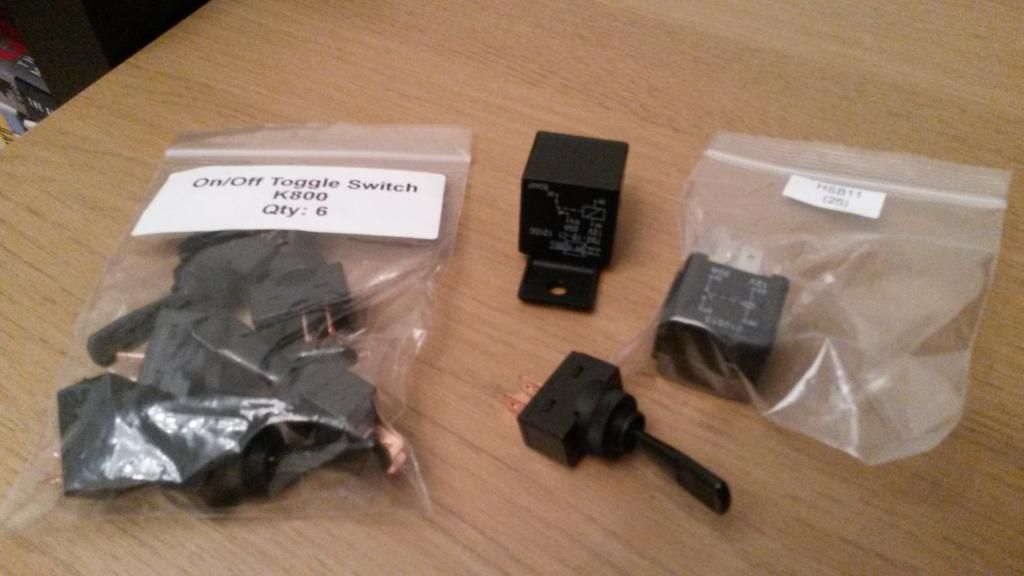
The new toggle switches and relays arrived today so I will get a picture of those posted up. I've also bought a batch of riv-nuts to redo the headlight bowls and to run the internal battery cables.


Next on my purchase list is a small sheet of carbon fibre to make a switch panel to match my carbon centre binnacle. 


Edited by LukeH, 13 February 2015 - 03:15 PM.


#32 LukeH

LukeH

    One Carb Or Two?

  • TMF+ Member
  • PipPipPipPipPipPipPip
  • 1,004 posts
  • Location: Norwich, Norfolk

Posted 16 February 2015 - 05:44 PM

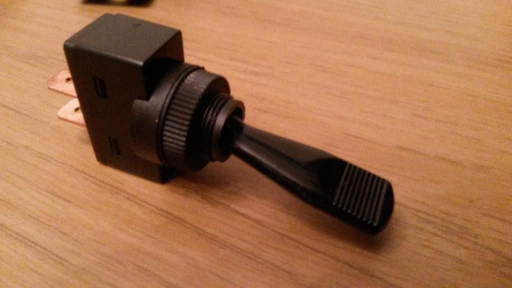
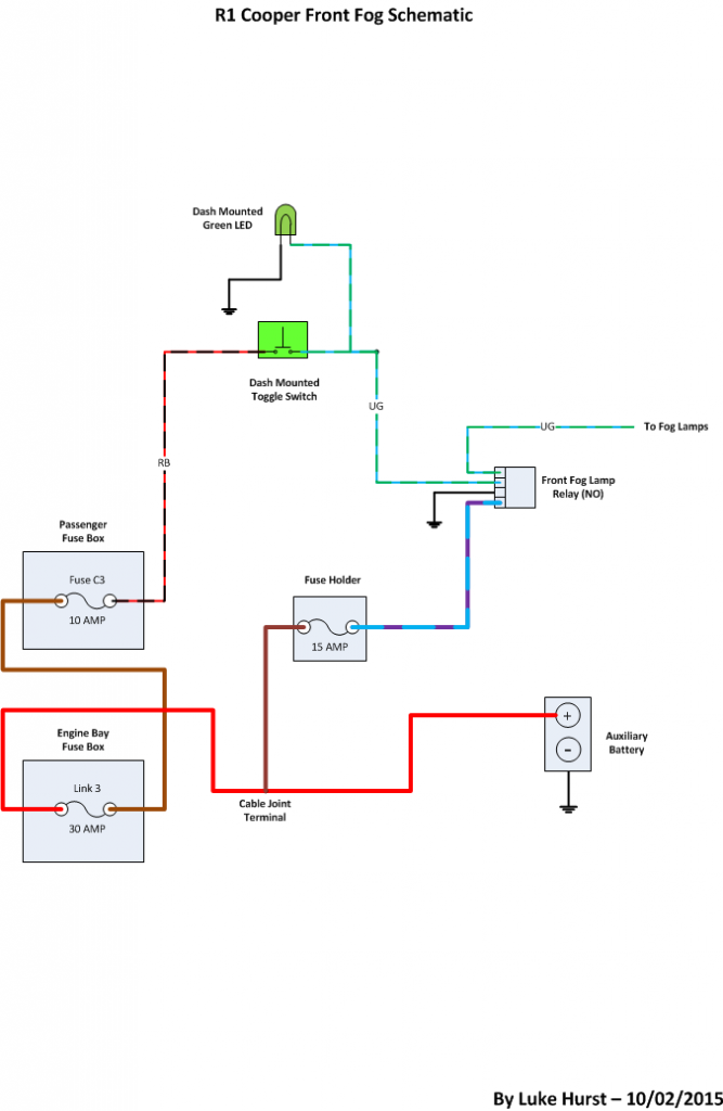
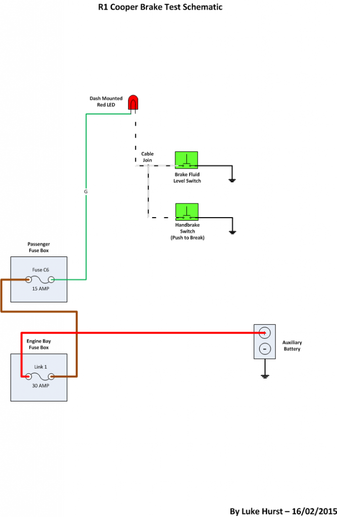
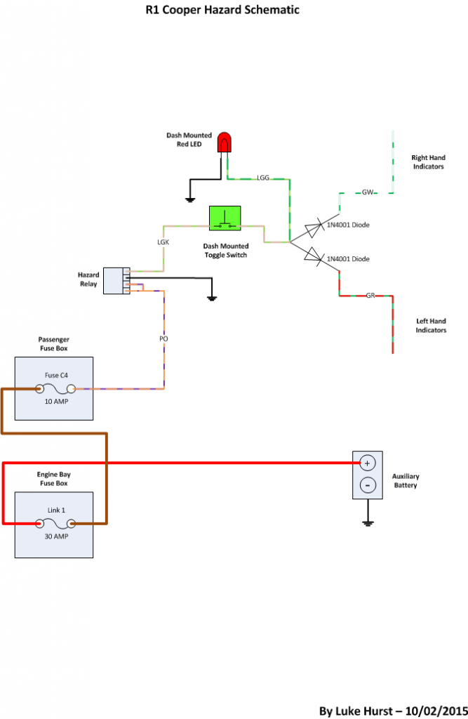
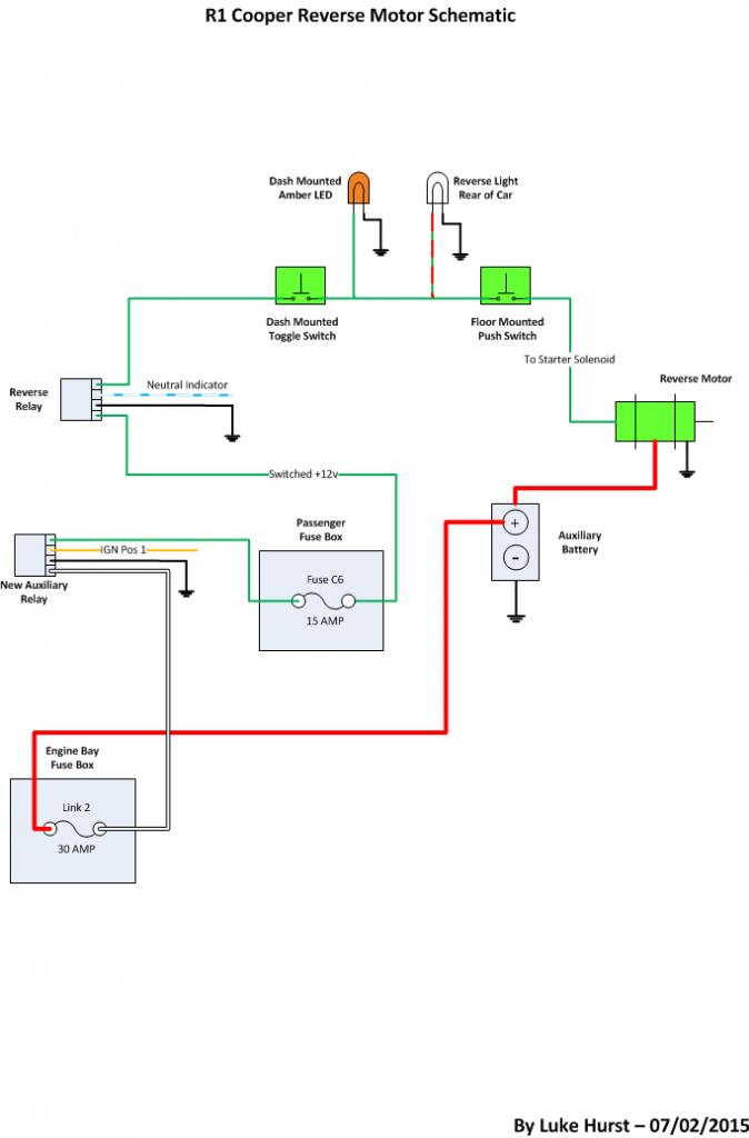
Here are few pictures of some of the bits and pieces I have ordered for the project. I am changing the rocker switches for toggle switches and separate LED's for the various warning lamps. I have created a schematic for each switch I plan to replace or add using a simple on:off switch and mixture of relays or diodes depending on the switch function.


20150213_182238.jpg


20150213_182247.jpg


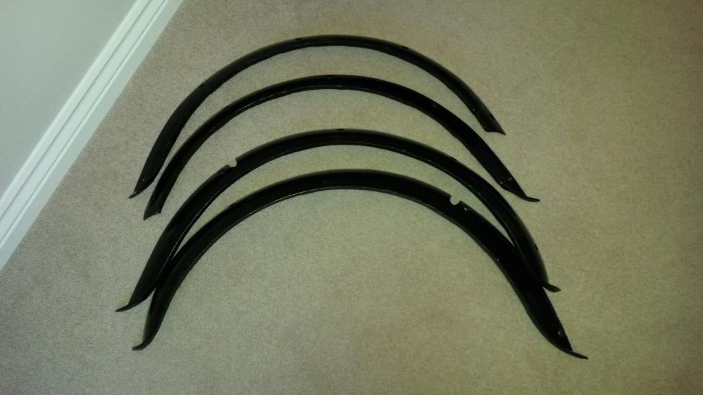
I also picked up some group 2 arches in the classifieds section as I plan to do a bit of MK1 styling


temp_1422624584424_-785781588.jpg


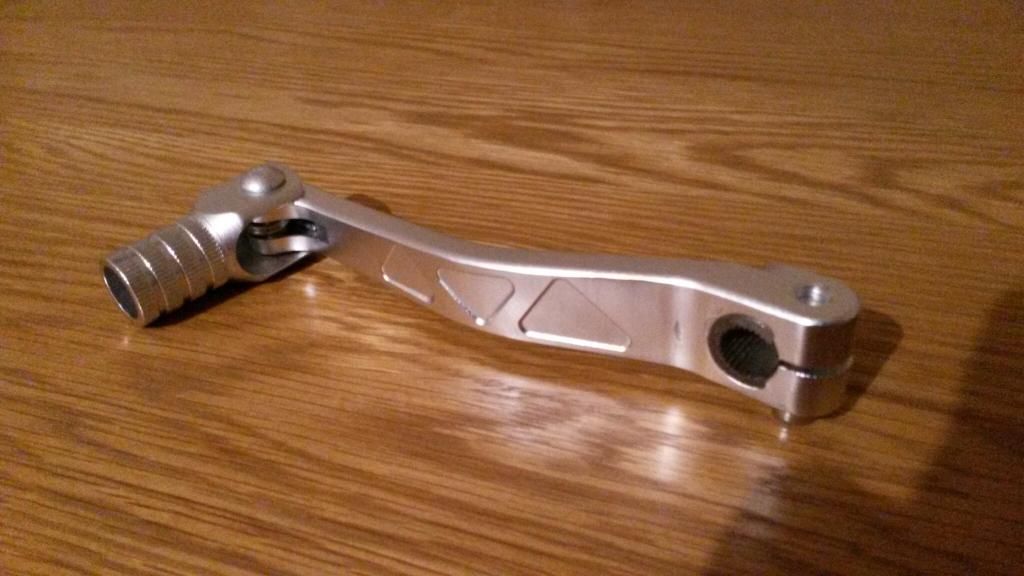
and finally the R1 engine I purchased didn't come with a shifter mechanism so I picked up this one ebay for £7. The spring loaded kick thing will be removed and then I will use rod ends to connect it to my custom sequential shifter when I get around to making it.


temp_1421953897204_-1048268170.jpg


#33 LukeH

LukeH

    One Carb Or Two?

  • TMF+ Member
  • PipPipPipPipPipPipPip
  • 1,004 posts
  • Location: Norwich, Norfolk

Posted 16 February 2015 - 05:58 PM

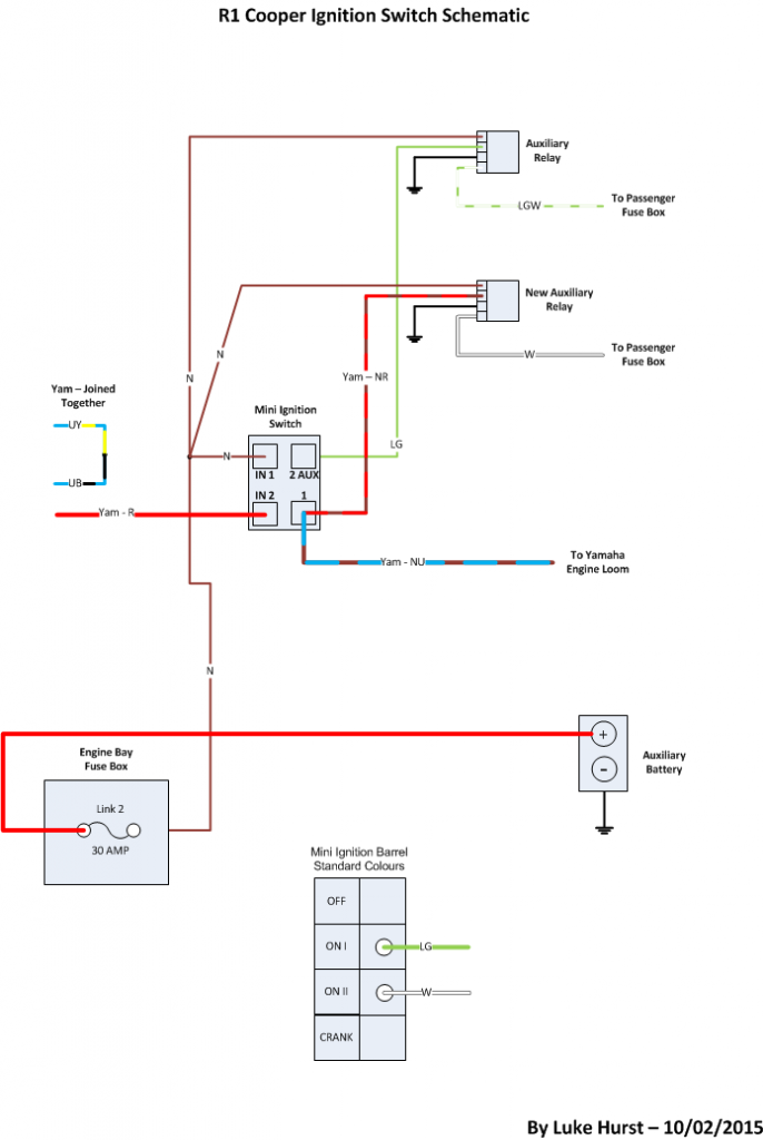
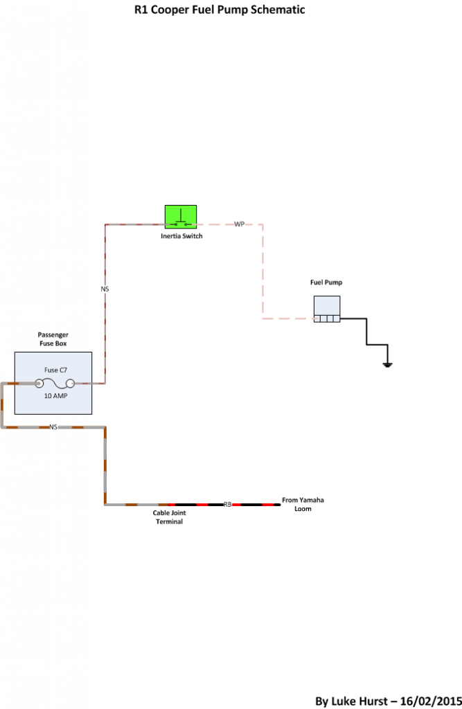
Here are all the drawings I have created so far for the various circuits I am changing or adding in. Hopefully they might prove useful for someone.  Note. My Mini is an MPI so colours and layouts might vary, Hazards for example.


Front Fog Toggle switch

FrontFogLightToggleSwitch-V2.png


Brake Test Circuit - No switch option using Handbrake

BrakeTestSchematic.png


Hazard light toggle conversion

HazardLightToggleSwitch.png


Electric Reverse

R1CooperReverseSchematic-V2.png


Ignition using MPI barrel and combining Mini & R1 loom

IgnitionSwitchWiringSchematic.png


R1 fuel pump circuit using Mini MPI inertia switch

FuelPumpSchematic.png


#34 LukeH

LukeH

    One Carb Or Two?

  • TMF+ Member
  • PipPipPipPipPipPipPip
  • 1,004 posts
  • Location: Norwich, Norfolk

Posted 27 February 2015 - 02:55 PM

Today I have taken a positive step towards actually starting the R1 install......I have ordered the steel so that I can build the engine cradle! I'm actually quite excited to go and collect the steel and start the fabrication.


#35 roadhouse

roadhouse

    Mini Mad

  • Noobies
  • PipPipPipPip
  • 106 posts
  • Location: Oklahoma

Posted 27 February 2015 - 03:32 PM

Today I have taken a positive step towards actually starting the R1 install......I have ordered the steel so that I can build the engine cradle! I'm actually quite excited to go and collect the steel and start the fabrication.


This is very exciting! Looking forward to seeing what you come up with. Good luck fabbing it all up...


#36 LukeH

LukeH

    One Carb Or Two?

  • TMF+ Member
  • PipPipPipPipPipPipPip
  • 1,004 posts
  • Location: Norwich, Norfolk

Posted 27 February 2015 - 03:35 PM


Today I have taken a positive step towards actually starting the R1 install......I have ordered the steel so that I can build the engine cradle! I'm actually quite excited to go and collect the steel and start the fabrication.


This is very exciting! Looking forward to seeing what you come up with. Good luck fabbing it all up...


Thanks I might need it. It's an ambitious DIY project but one I feel ready to take on. My backup plan is to just buy a cradle from Lynx if I don't succeed myself. 


#37 roadhouse

roadhouse

    Mini Mad

  • Noobies
  • PipPipPipPip
  • 106 posts
  • Location: Oklahoma

Posted 27 February 2015 - 08:15 PM


Today I have taken a positive step towards actually starting the R1 install......I have ordered the steel so that I can build the engine cradle! I'm actually quite excited to go and collect the steel and start the fabrication.


This is very exciting! Looking forward to seeing what you come up with. Good luck fabbing it all up...


Thanks I might need it. It's an ambitious DIY project but one I feel ready to take on. My backup plan is to just buy a cradle from Lynx if I don't succeed myself. 


Good to have a backup plan but I'm sure your engine cradle will turn out great. If I had any sort of fab skills I would go down your path but alas, I don't  :proud: Will be using the Lynx cradle.


#38 LukeH

LukeH

    One Carb Or Two?

  • TMF+ Member
  • PipPipPipPipPipPipPip
  • 1,004 posts
  • Location: Norwich, Norfolk

Posted 02 March 2015 - 02:26 PM

I have been giving the project some thought whilst I wait for the steel to arrive and I get enough time to make a proper start. I have come up with this rough plan of the tasks required. There is a lot more to actually do than what I have listed below but its a starting point at least.


I'm up to step 5/6 so far.....


1. Label MPI engine pipes and wires
2. Disconnect MPI engine
3. Remove MPI engine
4. Remove all unnecessary parts and wiring - document and update schematics 
5. Measure drive shaft positions - fabricate a gauge (length of wood)
6. Lift R1 engine in and line up
7. Measure clearance and mount points to create drawings
8. Fab main cradle strut and secure engine in position
9. Remove R1 engine
10. Disconnect subframe and remove from car
11. Fab metal cradle - use wood to prototype
12. Fab diff carrier
13. Fab reverse gear motor mount
14. Modify front panel for manifold clearance
15. Modify subframe for diff clearance & drive shaft pot joint clearance
16. Test fit subframe, cradle and engine in car
17. Modify drive shafts
18. Modify mini wiring loom
19. Modify R1 wiring loom
20. Convert R1 engine for BEC use - clutch, AIS removal etc...
21. Paint/powder coat subframe and cradle
22. Mount subframe, cradle and engine in car
23. Connect wiring harnesses
24. Connect cooling system
25. Test start


#39 LukeH

LukeH

    One Carb Or Two?

  • TMF+ Member
  • PipPipPipPipPipPipPip
  • 1,004 posts
  • Location: Norwich, Norfolk

Posted 04 March 2015 - 03:12 PM

I picked up the steel today and I have a week's annual leave next week so I can hopefully make a good start on the cradle fabrication.


#40 roadhouse

roadhouse

    Mini Mad

  • Noobies
  • PipPipPipPip
  • 106 posts
  • Location: Oklahoma

Posted 05 March 2015 - 09:03 PM

Excellent. I just called today to price the Lynx engine cradle and it's about 700 pounds. So you'll be saving quite to make one yourself  :proud:


#41 LukeH

LukeH

    One Carb Or Two?

  • TMF+ Member
  • PipPipPipPipPipPipPip
  • 1,004 posts
  • Location: Norwich, Norfolk

Posted 11 March 2015 - 08:08 PM

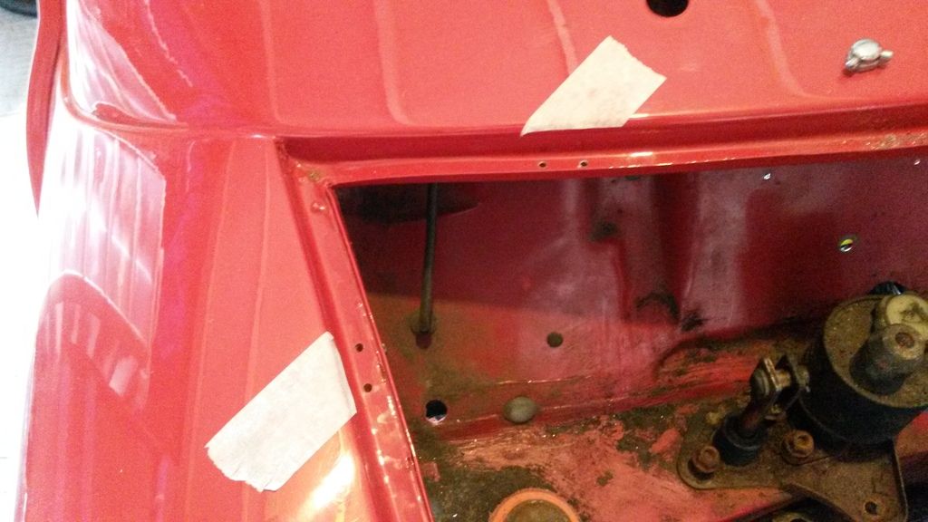
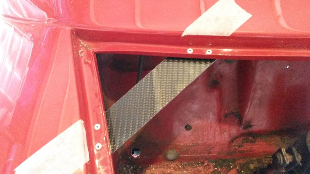
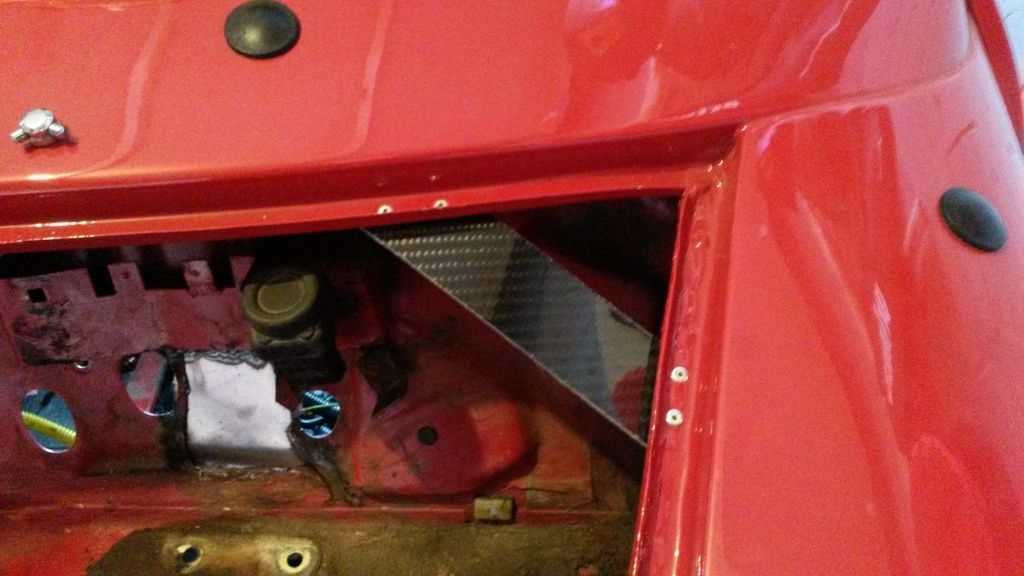
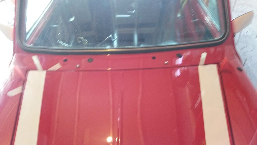
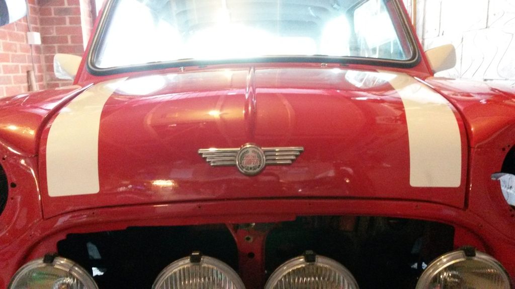
I got quite a lot done on the mini today starting with converting my bonnet to MK1 style. I painstakingly removed the grill lip without scratching the new paintwork and I ground off the various metal where the bonnet hinges and catches mount.

Next up was fabricating some brackets for the bonnet dzus fasteners I will be using on the back portion. I'm planning on leather strap at the front and the idea is to have the bonnet lift off.

I marked out the position and direction of the bracket using masking tape.

20150311_141103.jpg

Next I made a carboard template and cut.my carbon fibre to suit. Then I drilled and riveted in place.

20150311_141537.jpg

I then replicated on the nearside making sure I carefully measured and marked everything out.

20150311_151239.jpg

To make sure I got the bonnet lined up before drilling the pilot hole for the dzus fastener, I used some plastic packers. The picture is a bit fuzzy but the red 5mm and white 2mm packers should be visible.

20150311_143520.jpg

The finished look without fasteners fitted.

20150311_154844.jpg

I will be replacing the bonnet stripes with new longer ones

#42 LukeH

LukeH

    One Carb Or Two?

  • TMF+ Member
  • PipPipPipPipPipPipPip
  • 1,004 posts
  • Location: Norwich, Norfolk

Posted 11 March 2015 - 08:17 PM

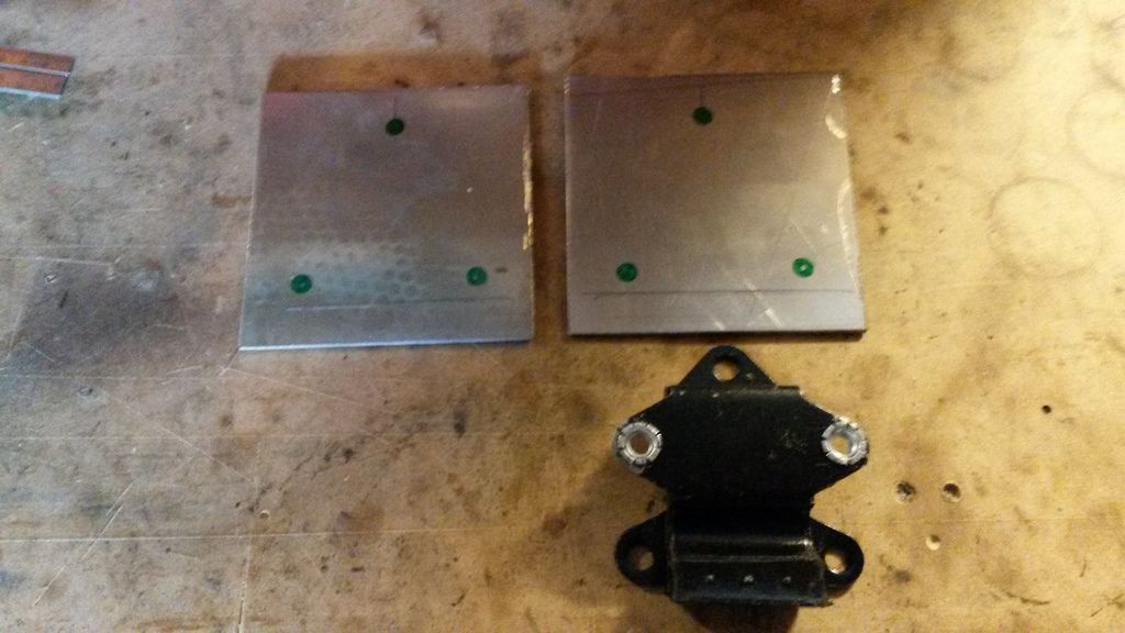
The engine cradle fabrication starts....slowly.

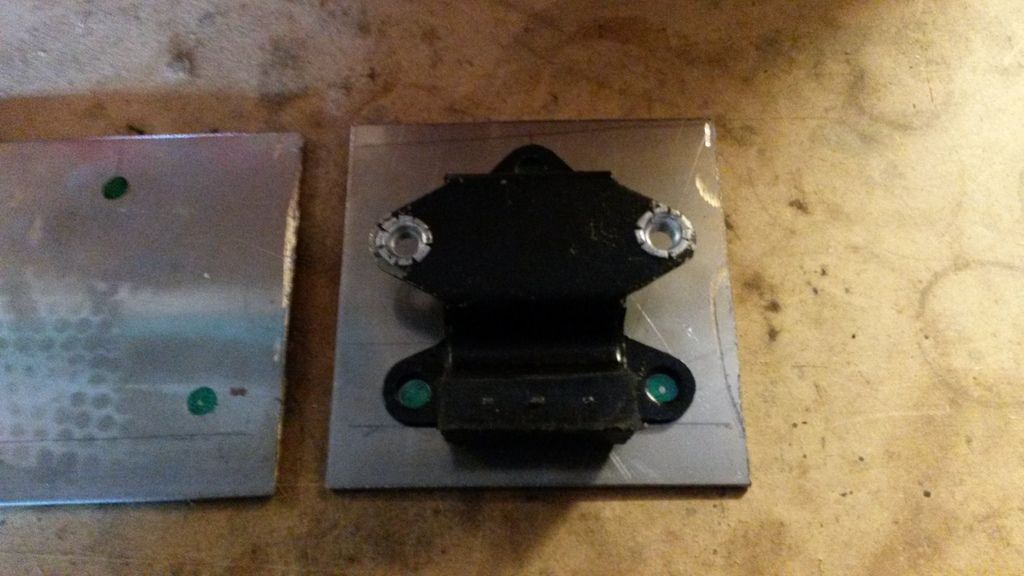
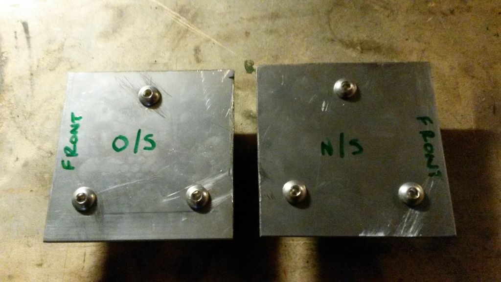
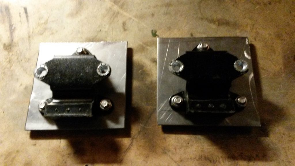
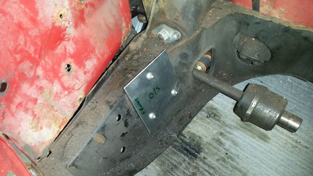
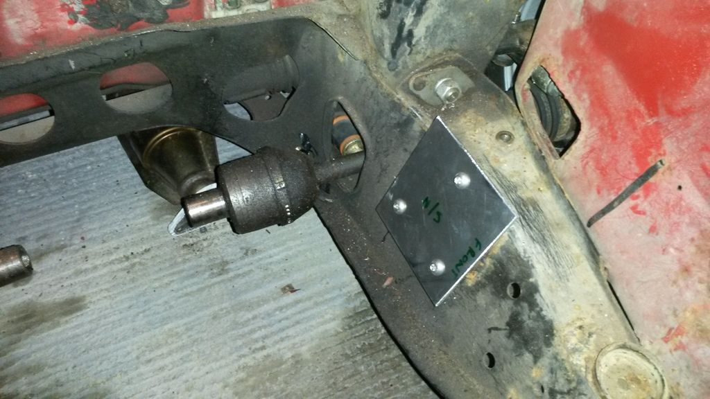
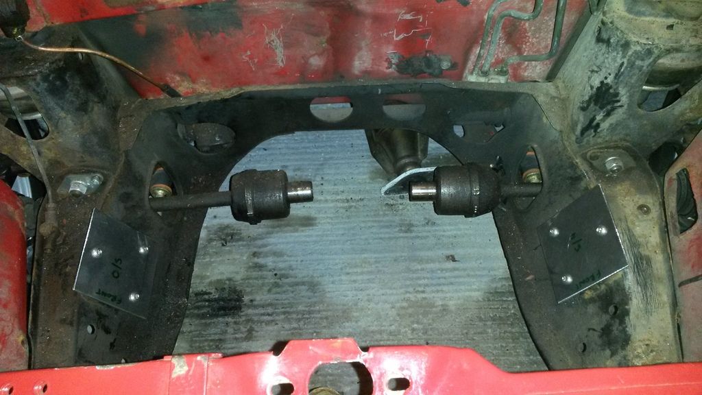
I managed to make a start on my engine cradle today, well sort of. I made up some metal plates out of 3mm steel that will form the starting the point of the cradle. The steel box section will weld onto these and they utilise the standard engine mount points and mounts.

I'll let the picture do the talking.

20150311_160347.jpg


20150311_160355.jpg


20150311_170352.jpg


20150311_170358.jpg


20150311_170658.jpg


20150311_170704.jpg


20150311_170708.jpg


#43 roadhouse

roadhouse

    Mini Mad

  • Noobies
  • PipPipPipPip
  • 106 posts
  • Location: Oklahoma

Posted 12 March 2015 - 01:38 PM

Nice start on the cradle. Slow progress is still progress...


#44 LukeH

LukeH

    One Carb Or Two?

  • TMF+ Member
  • PipPipPipPipPipPipPip
  • 1,004 posts
  • Location: Norwich, Norfolk

Posted 13 March 2015 - 04:17 PM

I attempted to lift the engine into the engine bay yesterday for the first time so I could start measuring up only to realise my crane won't fit between the wheels so it will need to be jacked up on axle stands.

This is a bit of a problem because I need the car sitting on the wheels to measure the ground clearance and engine position. It means I will have to jack car up, wheels off, engine in, wheels on, lower car every time i need the engine in place then reverse the process to give me space to work.

Hopefully I cab get everything measured and positioned so I can just remove the subframe and work on it outside the car.

#45 Ben_O

Ben_O

    Mill Road Garage

  • Paint Doctor
  • PipPipPipPipPipPipPipPipPipPip
  • 9,785 posts
  • Location: Isle of Wight

Posted 13 March 2015 - 05:10 PM

Could you not remove the front wheels and then  prop the car up so it is level as if the wheels were fitted?


Should be simple enough to measure from the top of the wheel arch to the ground with the car at rest on it's wheels and then match the measurement when propping it with the wheels off.


Might give you enough room to get the hoist under the front that way?


2 user(s) are reading this topic

0 members, 2 guests, 0 anonymous users