Mini Front Subfram Cad File
#16

Posted 28 November 2012 - 12:37 PM
#17

Posted 28 November 2012 - 03:11 PM
#18

Posted 29 November 2012 - 06:35 PM
#19

Posted 30 November 2012 - 09:48 AM
Edited by tom130691, 30 November 2012 - 09:49 AM.
#20

Posted 30 November 2012 - 11:57 AM
cant get it to open in 3d
on solidwork 2012
I can't open it in AutoDesk 3D Studio Max neither
#21

Posted 30 November 2012 - 12:18 PM
awesome file I must say!
#22

Posted 30 November 2012 - 01:40 PM
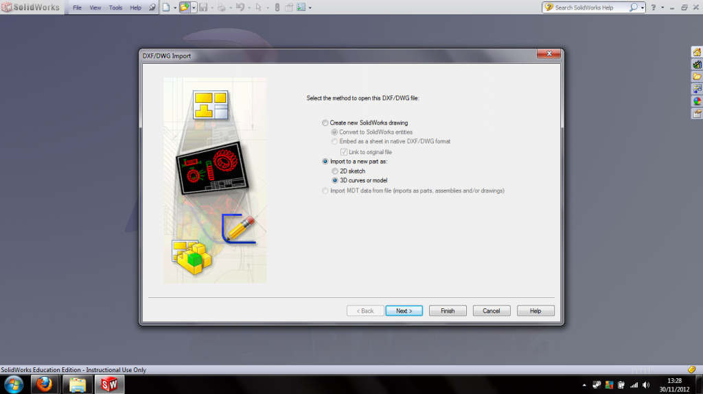
When you open the file, this should show up: Select "import to a new part as 3D curves or model"

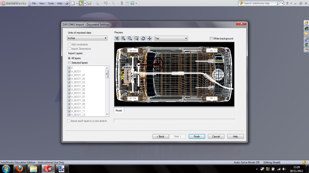
Next is this screen: simply click "finish"

Then, when its loading the file, this box should pop up: click "no"

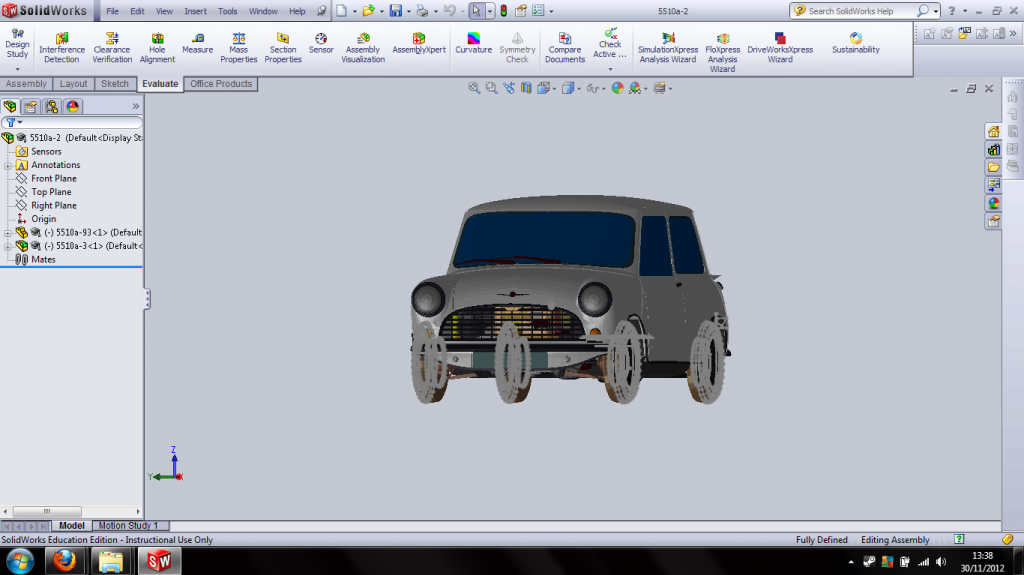
Then get ready for a long wait! Took around 20 mins to assemble on my laptop, after which you get this:

My advise is to immediately save it as its own assembly, so the computer dosent have to assemble it from all the parts every time you open it - only takes around 30 seconds to open on my laptop after doing this.
Edit: And yeah, it is a brilliant file, already spent quite a few hours messing round with it, especially the subframe file :)
Edited by miniman24, 30 November 2012 - 01:44 PM.
#23

Posted 30 November 2012 - 06:26 PM
#24

Posted 30 November 2012 - 06:30 PM
pm'd again.PM me email addresses
#25

Posted 02 December 2012 - 08:20 PM
tried catia and few other programs too but failed didnt try auto cad though
any chance some body could email me just the front suspension system
ill download autocad student version in a bit as it free and try opening it on my laptop. doubt it will open it if the uni computers in the engineering building failed :/
#26

Posted 02 December 2012 - 08:57 PM
It can be downloaded from the link below. Take a look on the blog page
http://www.minigtm.co.uk/
#27

Posted 02 December 2012 - 09:25 PM
That diagram of the mini sub frame is wrong. I used it an found it out to my cost. The model of my micra sub frame based on that diagram did not fit the model of my engine bay. I spent ages trying to find out what I had done wrong and it turned out to be that diagram. It isn't out by just a little bit, its out by quite a lot.
Its either that diagram is wrong or my mini is seriously wrong. If my mini is seriously wrong then my sub frame must be as well.
I think the problem is that the plan view is not perpendicular to the side view. I think its out by about 8 degrees or something. In the end in my MSc work I dismantled my mini's sub frame and measured it.
#28

Posted 04 December 2012 - 12:51 AM
But thanks for the heads up MJWJ
Charlie
#29

Posted 04 December 2012 - 11:03 AM
#30

Posted 04 December 2012 - 02:39 PM
What a file! Thanks!
1 user(s) are reading this topic
0 members, 1 guests, 0 anonymous users


