A wound field motor will always run the same way regardless of polarity. (They also run happily on AC if the magnetic circuit is laminated to minimise eddy current losses. Don't try it with car type motors with solid iron magnetic circuit.) To reverse one, you need to reverse the armature or the field, not both. If the wiper motor really was running backwards, the parking position would be wrong, as the setting of the parking switch allows for motor inertia when running in the correct direction.
However, many modern vehicles (including later Minis?) use more efficient permanent magnet motors in some places, which do need their polarity reversing. Such vehicles will invariably be negative earth anyway.
I would recommend a new set of points after polarity reversal, as they tend to erode badly. You will all have seen that in normal use, you get a small crater on one contact and a pip on the other. Reverse the metal transfer and you get both becoming very rough quite quickly.
Beware of all electronic devices, i.e. radios, many tachometers, etc, which need correct polarity.
Don't forget that the battery terminals are, or should be, different sizes. Now is the time to replace them, if they are the old and unreliable pot type, withh the easily available clamp type.


Positive Earth To Negative
Started by
Mk1Ruby
, Jul 16 2012 09:31 AM
33 replies to this topic
#16

tiger99
-

- Members
-

- 8,584 posts
Crazy About Mini's
- Location: Hemel Hempstead
Posted 19 July 2012 - 03:29 PM
#17
mister bridger
-

- Traders
-
- 911 posts
One Carb Or Two?
- Location: Hastings
Posted 19 July 2012 - 03:46 PM
Just discovered mine is +ve earth when fitting a tacho. Didn't have a clue! Not too bothered about it though I seem to remember reading that +ve earth cars corrode worse - something to do with anodes or cathodes or commodes or something - any truth in this?
#18
Ethel
-

- TMF Team
-
- 25,821 posts
..is NOT a girl!
- Local Club: none
Posted 19 July 2012 - 04:00 PM
The wiper motor won't run backwards because of the ramp for the park switch.
I admit I was struggling to understand the motor issue, until DK pointed out the field coils.
I guess screen washer pumps might be an exception - their connectors suggest polarity matters.
I admit I was struggling to understand the motor issue, until DK pointed out the field coils.
I guess screen washer pumps might be an exception - their connectors suggest polarity matters.
#19
tiger99
-
- Members
-
- 8,584 posts
Crazy About Mini's
- Location: Hemel Hempstead
Posted 19 July 2012 - 07:06 PM
Ethel,
Thank you for mentioning that, as I had overlooked washer motors, which are small, and very likely to be permanent magnet (just like "toy" motors, which is more or less what they are), even on an older car, so they will need wires reversing. Window motors too, probably.
In small sizes, permanent magnet motors are all that is practicable, as winding a very small field is difficult, and in any case the required power output and efficiency are modest. In larger sizes, all the way up to railway locomotives, wound field was more efficient than having very large and heavy cast magnets, and easier to control by varying field current only, to get different speeds, but that all changed when better magnetic materials and very inexpensive solid state PWM speed controllers arrived.
As far as I am aware, all brushless DC motors, the current fashion, are permanent magnet (no sense in needing brushes to feed the winding on the rotating component, having abolished the commutator), but of course these need the polarity to be correct to suit the electronics anyway. Some people use computer type brushless fans in their ventilation systems, which introduces another issue, their tolerance to transient overvoltage, which in a typical car can be about 45 volts peak if the alternator is suddenly relieved of a large load like headlamps. In a PC, these 12V fans never, ever see more than about 13.5V.
#20
dklawson
-

- TMF+ Member
-
- 10,923 posts
Moved Into The Garage
- Name: Doug
- Location: Durham, NC - USA
- Local Club: none
Posted 19 July 2012 - 07:41 PM
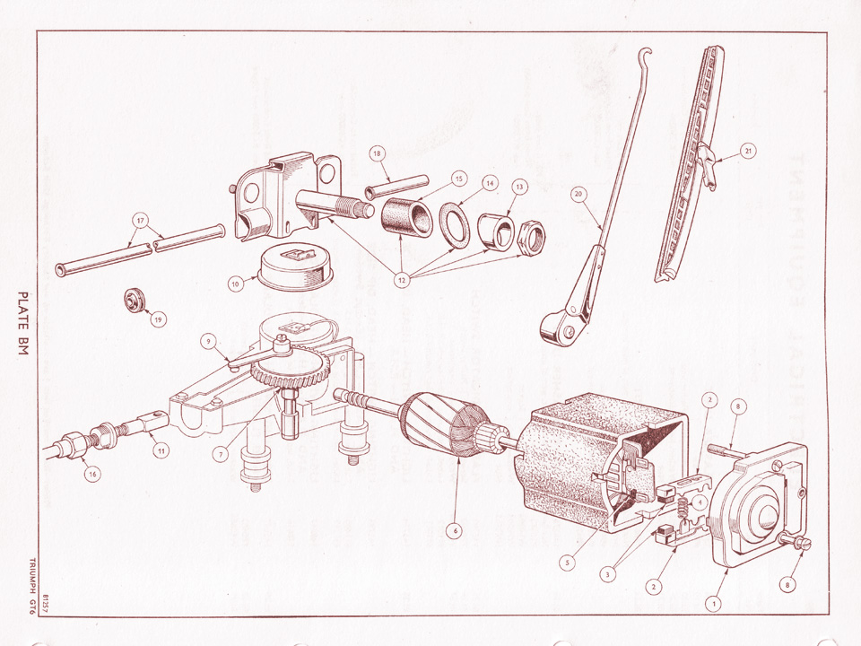
In this case, on a Mini where you are concerned about switching from positive to negative earth, the car will be equipped with a "DR" series square wiper motor (DR2 or DR3?). Those are not permanent magnet either. They have a single large field coil offset in the rectangular housing. So even they will not change the direction of rotation when the polarity is reversed.
Exploded DR3 in the link below:
http://www.canleycla...ly_plate_bm.jpg
DR3 wiper motor wiring at the bottom of the page in the link below:
http://www.stretton..../DR1 motor.html
Video showing the insides of a DR3 motor (3rd video down on the page in the link below):
http://jagxketype.bl...fixed-head.html
#21
mister bridger
-
- Traders
-
- 911 posts
One Carb Or Two?
- Location: Hastings
Posted 11 September 2012 - 07:41 AM
Just done this on my 67 mk1, and all went well with the exception of......... electric fuel pump needs wires reversing, as I found after it ran for a minute or so then conked out due to lack of fuel! Also my aftermarket tacho has packed up.
#22
pdaykin
-
- Members
-
- 587 posts
Super Mini Mad
Posted 11 September 2012 - 08:41 AM
All this detail talk without mentioning Flemming !!!!
Anyway, back to the main discussion. Changing polarity is a very straight forward process - the early minis have so few "toys" that there is very little to complicate it. No washer jet pumps, no electric windows, no fancy gauges, etc.
As Mr Bridger noted, it is really only the fuel pump - even then, some of the aftermarket pumps do not need the connections swapping over.
The aftemarket accessories are the real issue - radios, tachos etc. Some tachos can be connected for either +VE or -VE earth (sadly mine cant, so as I like the period look it isnt wired).
#23
Barman
-

- Members
-
- 1,068 posts
One Carb Or Two?
Posted 11 September 2012 - 08:48 AM
All this detail talk without mentioning Flemming !!!!
Anyway, back to the main discussion. Changing polarity is a very straight forward process - the early minis have so few "toys" that there is very little to complicate it. No washer jet pumps, no electric windows, no fancy gauges, etc.
As Mr Bridger noted, it is really only the fuel pump - even then, some of the aftermarket pumps do not need the connections swapping over.
The aftemarket accessories are the real issue - radios, tachos etc. Some tachos can be connected for either +VE or -VE earth (sadly mine cant, so as I like the period look it isnt wired).
I am holding my hand out now!

#24
dklawson
-
- TMF+ Member
-
- 10,923 posts
Moved Into The Garage
- Name: Doug
- Location: Durham, NC - USA
- Local Club: none
Posted 11 September 2012 - 12:29 PM
Concerning the fuel pumps, this is not necessarily (or safely) handled by swapping wires.
It is true that some of the original SU electric pumps are polarity sensitive. Originally the pumps were mounted in a metal clamp covered with a layer of rubber. That rubber does insulate the pump from earth but that is not its purpose. It is primarily there to dampen noise and provide a sure grip for the mount.
Underneath the black plastic cover on the end of the pump you will find three possible configurations: a capacitor across the pump's points, a diode across the pump's points, or nothing across the pump points. You are most likely to find one of the first two options. With the capacitor or diode it is necessary to disconnect the component and switch its wire connections (end to end) when you change the car/pump's polarity. That retains the functionality and allows the pump body to still be at earth potential.
The same applies to most early electronic tachometers. There are a couple of components that have to be "switched" inside the tach to insure the circuit board is properly powered. This is most common with the Smiths RVI tachometers. However, some of the earliest Smiths RVC type may also be affected. There are web sites out there that detail the component changes required for both Smith tachs and for the SU pumps.
#25
Pete649
-

- TMF+ Member
-
- 375 posts
Speeding Along Now
- Location: Isle of Man
Posted 12 September 2012 - 05:31 PM
Some people use computer type brushless fans in their ventilation systems, which introduces another issue, their tolerance to transient overvoltage, which in a typical car can be about 45 volts peak if the alternator is suddenly relieved of a large load like headlamps. In a PC, these 12V fans never, ever see more than about 13.5V.
Thanks for the heads up on this. I was about to fit a PC fan to my vent system.
#26
Yoda
-

- Traders
-
- 1,958 posts
Camshaft & Stage Two Head
- Location: Dartford, Kent
- Local Club: Medway mini club
Posted 12 September 2012 - 05:35 PM
Feed the fan from the voltage regulator! constant 10 volt supply is fine for a pc fan.
#27
dklawson
-
- TMF+ Member
-
- 10,923 posts
Moved Into The Garage
- Name: Doug
- Location: Durham, NC - USA
- Local Club: none
Posted 13 September 2012 - 02:58 AM
Feed the fan from the voltage regulator! constant 10 volt supply is fine for a pc fan.
I believe you mean the voltage stabilizer that supplies the fuel and temperature gauges.
While it may sound like a good way to supply a bit of electronics, the original Smiths (and Nippon Seiki) voltage stabilizers are actually quite noisy and would not be my first choice for power... at least not if the electronics were "picky". The way the stabilizer produces 10V is to switch on and off rapidly. The output isn't a steady 10V it's more like a bunch of nominal 12V peak square waves whose average amplitude works out to be about 10V.
Tiger, how about fitting a transient voltage suppressor across the brushless fan power input to sink the spikes?
#28
mattbeddow
-

- TMF+ Member
-
- 335 posts
Speeding Along Now
- Location: Warwickshire
Posted 16 September 2012 - 10:35 AM
you should be able to find pc fans that take 12v, (a pc's psu will output 5 and 12v over the molex connector so its just a case of finding one that takes 12v), failling that, rip the electrics out of a cigar usb charger to get a nice clean 5v
#29
dklawson
-
- TMF+ Member
-
- 10,923 posts
Moved Into The Garage
- Name: Doug
- Location: Durham, NC - USA
- Local Club: none
Posted 16 September 2012 - 03:00 PM
you should be able to find pc fans that take 12v, (a pc's psu will output 5 and 12v over the molex connector so its just a case of finding one that takes 12v), failling that, rip the electrics out of a cigar usb charger to get a nice clean 5v
I believe Tiger's point was that the common 12V PC fan is a brushless DC design that is not expecting to see the voltage spikes that occur in an automotive environment. The unexpected spikes (which won't be present on a well regulated PC's power supply) can damage the brushless DC PC fan.
#30
tiger99
-
- Members
-
- 8,584 posts
Crazy About Mini's
- Location: Hemel Hempstead
Posted 16 September 2012 - 03:02 PM
The instrument voltage regulator can not supply a fan, and will fail quite rapidly. Sadly, a transient suppressor will not be able to deal with the long, slow spikes common in car electrical systems. They are very good for short, sharp spikes, but that is all.
Give me a few days and I will design, and test by simulation, a circuit that will do the job. I need one myself soon, for a different car anyway. You will need to have some experience of building electronic circuits to make one.
And, Doug is correct, it is the cheap electronics in a brushless fan that can't take much overvoltage. A normal DC motor would come to no harm at all.
Edited by tiger99, 16 September 2012 - 03:04 PM.


3 user(s) are reading this topic
0 members, 3 guests, 0 anonymous users


