Hi, I've found an odd problem after doing the mod in "How To Fix Your Nippon S' Temp And Fuel Gauges".
link here... http://www.theminifo...ulator maplins
After new senders and no joy I did this mod and now my guages are a bit too good!!
The fuel guage is a bit too keen to stay high when full its off the guage until its tank is 1/2 full and then it works kinda like it should, so thats ok I can live with that... but the temp guage climbs into the red as soon as the car gets to 88-90 and thats a good operating temp but the guage says its red to dead!
I've checked the sender and its fine on the resistance. warming up lowers the resistance so normal tickover running temp eventually gives me about 80 something ohms, so this seems ok and it is a new sender too.
Is it worth adding a resister to the sender so bring the guage back down to the middle as I know the engine ain't overheating.
I'm thinking the now constant 10v would be stronger than the old 10v output because the old style reg would average less than 10 due to it's switching on and off all the time.
Maybe the new regulator should give 9.5v instead of 10v so it all works more like it used too?
the guages work fine, senders too, and the maplins regulator is a steady 10v.
what do you think folks?
can i get away with a resister to drop the voltage a lil bit so I still have guage to move up into if I ever overheat? y'know so my temp guage shows mid line when normal and only gets to the red if its seriously hothothot!


Odd Problem After This Mod "how To Fix Your Nippon S' Temp And Fuel Gauge"
Started by
novakor
, Apr 02 2012 06:54 PM
16 replies to this topic
#2

novakor
-
- Noobies
-

- 46 posts
On The Road
- Location: staffordshire
Posted 02 April 2012 - 06:56 PM
oh its a 1989 mini city e in great nick by the way (forgot to mention that)
and the mod was done as described and checked lots with multimeter,,,
and the mod was done as described and checked lots with multimeter,,,
#3
novakor
-
- Noobies
-
- 46 posts
On The Road
- Location: staffordshire
Posted 03 April 2012 - 06:05 AM
bump
#4
Bungle
-

- Members
-
- 28,971 posts
Original Spamster
- Location: Cornwall
- Local Club: cornish mini club
Posted 03 April 2012 - 06:37 AM
try a PM to the original poster of that topic stormintrooper
#5
stormintrooper
-

- Members
-
- 2,072 posts
Up Into Fourth
Posted 03 April 2012 - 11:33 AM
Hiya yes, thank you for bringing this back to my attention, the thread needs to be removed or hidden for the time being, as you suggest novakor, the constant 10V works too well than the on off of the smiths type of regulator, therefor giving it a too high a reading than the actual temperature, same will apply for your fuel gauge too! so please dont think you have a quarter a tank left because you probably have none lol
However, by all means experiment if you want, you may have some better luck than i, a small resistor may do the job, best thing i can think for you to try (as im no longer in a position to try anymore) is make sure you have a full tank, play around with a variable resistor until your needle just reaches the full mark, empty out half the tank and see what happens, if you have luck repost your findings please so i could make amendments to my original thread
However, by all means experiment if you want, you may have some better luck than i, a small resistor may do the job, best thing i can think for you to try (as im no longer in a position to try anymore) is make sure you have a full tank, play around with a variable resistor until your needle just reaches the full mark, empty out half the tank and see what happens, if you have luck repost your findings please so i could make amendments to my original thread
#6
novakor
-
- Noobies
-
- 46 posts
On The Road
- Location: staffordshire
Posted 03 April 2012 - 07:13 PM
thanks for getting back to me stormtrouper!
I'm about to change my bulbs to leds while I have the guages out so I'm going to try a resister on the maplin chips 10v output to drop the voltage to guages to 9v when I do, (this weekend hopefully).
I'll be sure to post the results of my multimeter!
:)
I'm about to change my bulbs to leds while I have the guages out so I'm going to try a resister on the maplin chips 10v output to drop the voltage to guages to 9v when I do, (this weekend hopefully).
I'll be sure to post the results of my multimeter!
:)
#7
Dan
-

- TMF+ Member
-
- 21,354 posts
On Sabbatical
Posted 03 April 2012 - 07:25 PM
This is an interesting development, and not one that I was expecting. The gauges are calibrated to operate at exactly 10v, the switching action of the stabliser is what develops the 10V RMS, not something that would reduce it below that. Read this - http://home.mindspri...eStabilizer.pdf from our own DKLawson about the gauges. AFAIK the only thing that might be a problem is the load on the regulator. Exactly what chip are you guys using and what is its power rating? Have you arranged heat sinking for the chip? The two gauges are surprisingly power hungry and together could be drawing as much as 8W from the system. If that's what's causing the problem, adding resistors is only going to load the system further and make it worse.
#8
novakor
-
- Noobies
-
- 46 posts
On The Road
- Location: staffordshire
Posted 03 April 2012 - 09:12 PM
once I dig some resistors or some diodes from my tinkering box I'll have a play over the weekend and let you know :)
If creating a voltage drop adds to the problem the my next step is to try a maplin chip that give more voltage like say 11v. but I think this is unlikely as the guages are already getting too much of whatever the problem is.
The guages work on bimatalic strips that move as they heat up (I think).
The guages are getting either too much voltage or too much current as one of these is deflecting the real reading significantly.
So the problem might even be that they like a sweet 10v but need less current?
(based on the old regulator design being intermitent on its output)
The chip in the mod post gives 10v at 1000ma or 1amp so maybe some tinkering is the best way to find that sweet spot!
I'll try a voltage drop first as this should also reduce the current slightly at the same time.
once we experiment together we could find an average setup that works and then find the perfect regulator chip!!
If you've done this mod PLEASE experiment and tell us your results so we can find the perfect component!
#9
dklawson
-

- TMF+ Member
-
- 10,923 posts
Moved Into The Garage
- Name: Doug
- Location: Durham, NC - USA
- Local Club: none
Posted 04 April 2012 - 12:17 PM
Go online and find a datasheet for the chip you bought. Look carefully at Stormintrooper's article and compare the article to both your gauge cluster AND the pin out as shown on the datasheet.
Stormin' put a lot of effort into his work but if I remember correctly he used all the same wire colors so you have to pay very close attention to "what goes where" when looking at his article. Make sure that you actually have the chip earthed, 12V power going in on its input leg, and that its 10V output leg is connected to the gauge power trace.
If the chip is wired incorrectly it will do 2 things. It will typically get VERY hot and you will have 12V where you are NOT expecting it. If the voltage is too high... your gauges will read high just like you are reporting. Also remember that you have to put the shim/insulation between the old Nippon-Seiki voltage stabilizer points.
#10
stormintrooper
-
- Members
-
- 2,072 posts
Up Into Fourth
Posted 05 April 2012 - 11:34 AM
i did use 2 colours for 3 wires as i only had 2 lying around but they were clearly labelled
#11
dklawson
-
- TMF+ Member
-
- 10,923 posts
Moved Into The Garage
- Name: Doug
- Location: Durham, NC - USA
- Local Club: none
Posted 05 April 2012 - 12:14 PM
Remove the chip from wherever it is mounted, connect its wires to an earth an power connection (per the datasheet) then confirm the output terminal has 10V on it.
After that, you will need to double-check Stormin's connections on the back of the gauge cluster. You will need to confirm that the trace he used for earth is indeed earth, that the power in does have switched 12V on it. Also make sure the old NS stabilizer had the insulating material between its points. I cannot offer any hands-on guidance for the FAQ and wiring of the chip to the NS clusters. Cars with the NS clusters never made it over here except when imported one at a time... typically with questionable paperwork.
After that, you will need to double-check Stormin's connections on the back of the gauge cluster. You will need to confirm that the trace he used for earth is indeed earth, that the power in does have switched 12V on it. Also make sure the old NS stabilizer had the insulating material between its points. I cannot offer any hands-on guidance for the FAQ and wiring of the chip to the NS clusters. Cars with the NS clusters never made it over here except when imported one at a time... typically with questionable paperwork.
#12
novakor
-
- Noobies
-
- 46 posts
On The Road
- Location: staffordshire
Posted 05 April 2012 - 06:28 PM
All helpful words and thanks for the help!
I'll be back with tales of my tinkering asap :)
I'll be back with tales of my tinkering asap :)
#13
novakor
-
- Noobies
-
- 46 posts
On The Road
- Location: staffordshire
Posted 07 April 2012 - 03:34 PM
Because some of the bulbs in the dash need work both ways and an LED only works one way I decided to only change the dial bulbs and the indicator bulbs. Luckilly they work very well with the new 10v setup and I found that LEDs are very directional.
This means that the guages were brighter with the origional incandecent bulbs!
Right then it's time to open things up and sort em out...
This means that the guages were brighter with the origional incandecent bulbs!
Right then it's time to open things up and sort em out...
#14
novakor
-
- Noobies
-
- 46 posts
On The Road
- Location: staffordshire
Posted 07 April 2012 - 03:39 PM
Ok folks here's my guage tinkering...(hope it's not too long winded)
Opened up the instrument cluster to check that the old voltage regulator was still isolated with a bit of tape as described in the origonal mod. Yep all ok there , and the new voltage regulator chip was wired correctly and still giving out a constant 10v so thats all good :)
Voltage at the temp sender is 9.86v
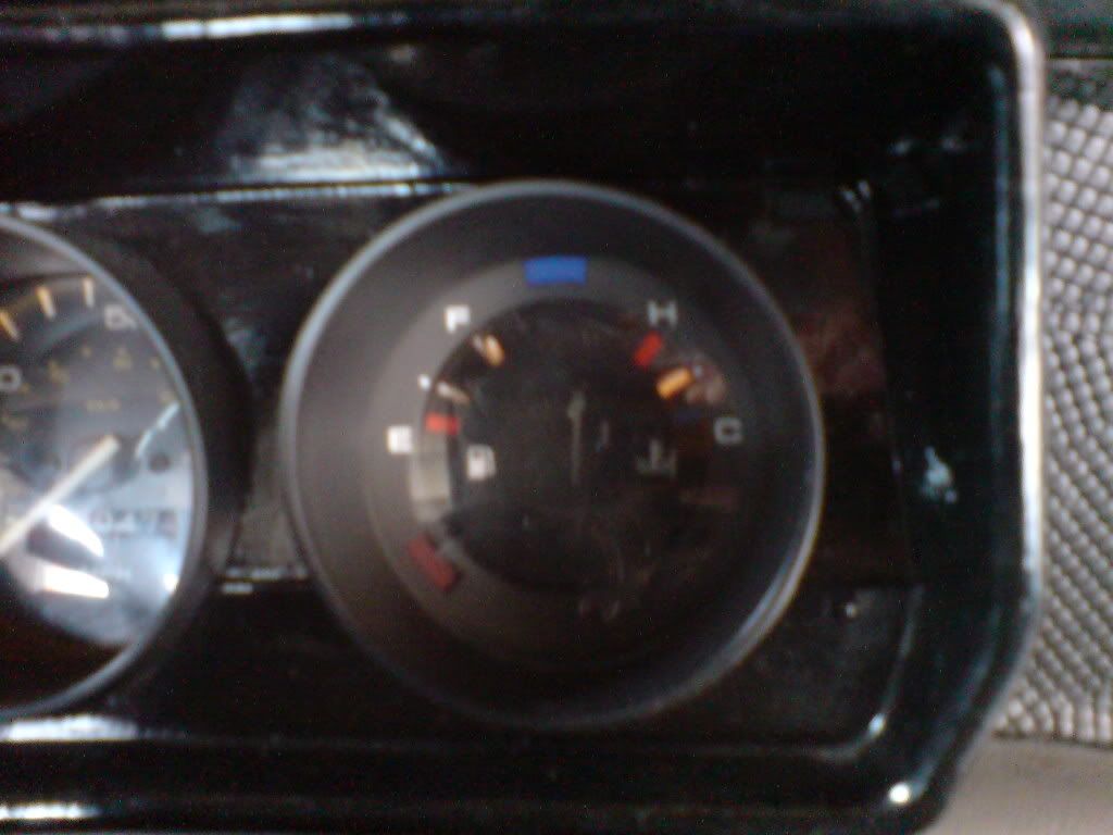
Checked the resistance of the temp sender as the car warmed up and this was within expected norms and the temp guage slowly climed its way up until at normal running engine temp the guage was steady just under the red bit.
When I drive my mini hard up a few hills the temp guage climbs a little so that it's just above the red bit.
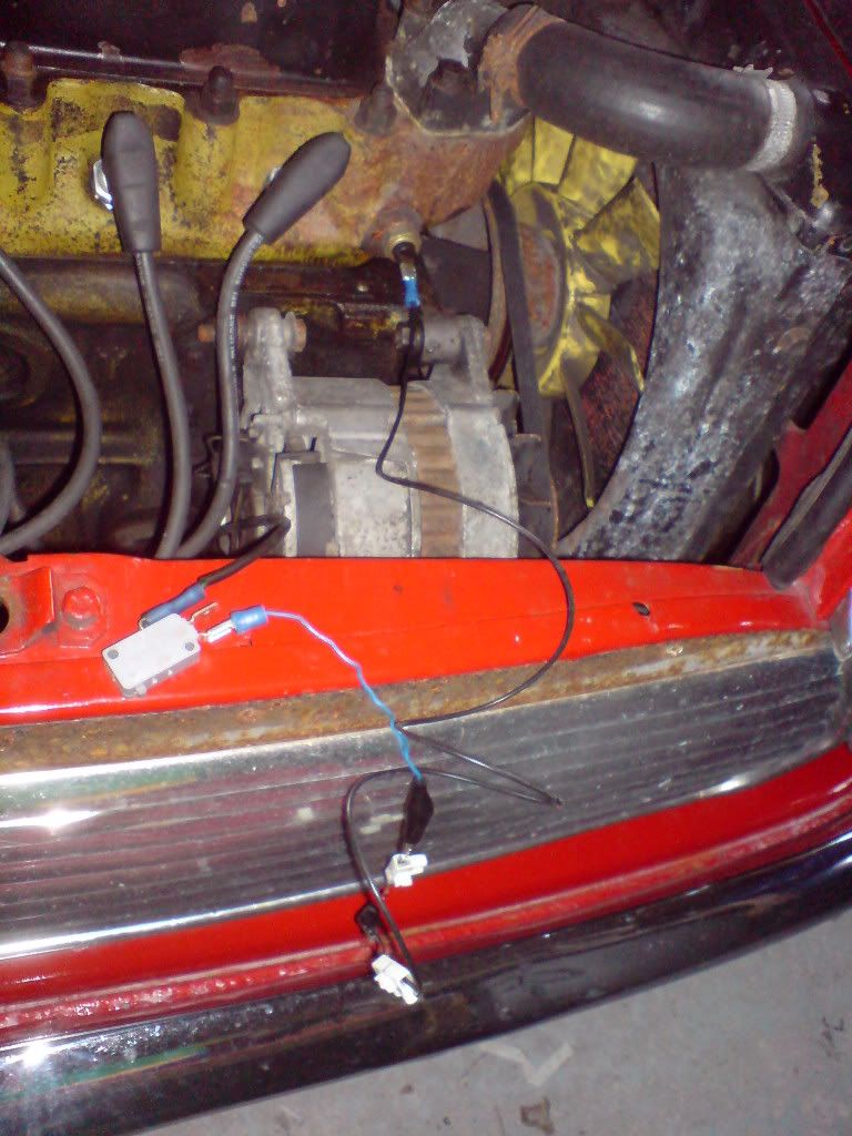
I know the engine isn't overheating so I crimp up some crocodile clips so I can insert different resistors in line with the sender wire.
And then one by one I test every kind of resistor I can get my hands on to see if I can change the deflection of the needle.
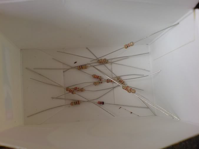
Lots of wasted time later I find that not even one of them lets through enough current to let the guage even function! now what!?
Then I remember that diodes also create a voltage drop and I try a few of those instead.....and results!!
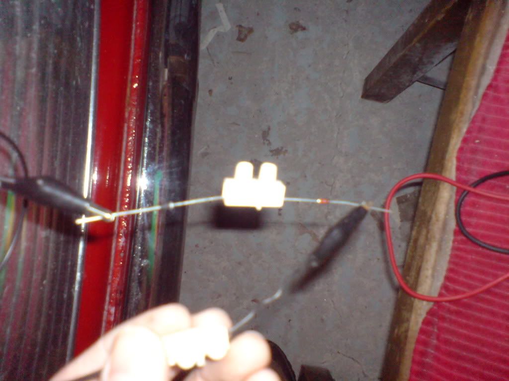
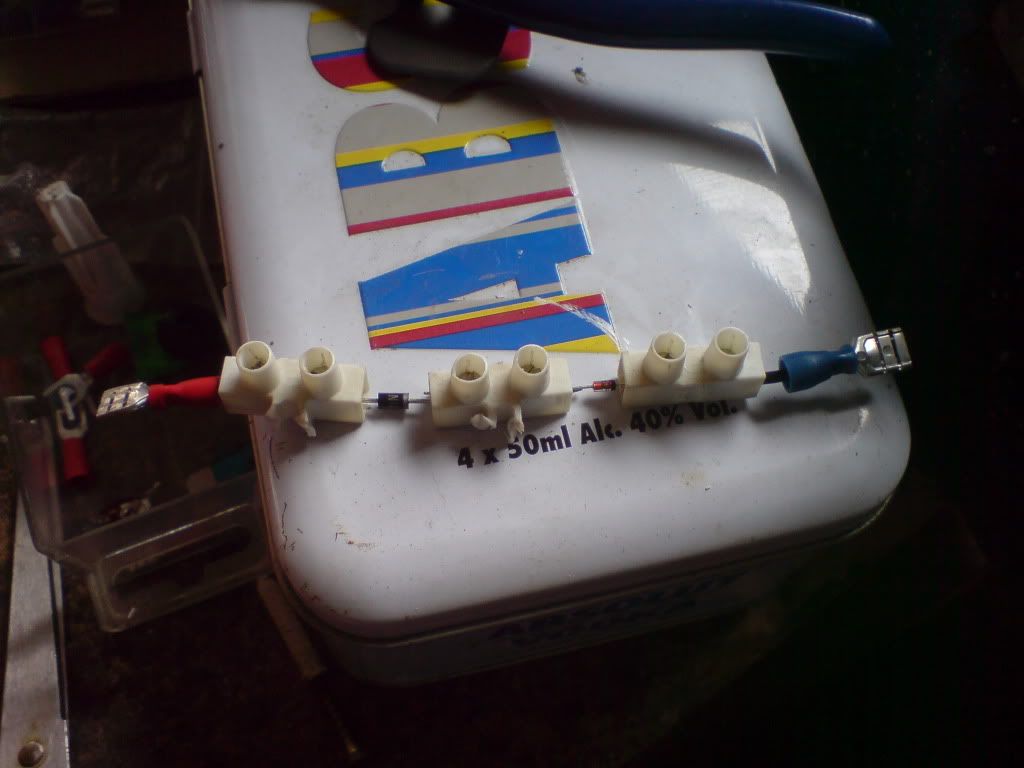
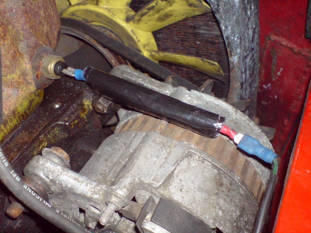
The comination of two diodes in the above pictures drop the voltage down to 7.61v at the sender and this puts the temp guage back where it should be on the center line :)
Time to tidy up the diodes a bit so some choccy block, wire, spade conectors, then wrap in bubble wrap and cover in bodge tape and I have a component that only flexes by the wires at each end and is protected from engine heat and should be ok in the rain.
And should it fail I can just plug the wire back on the sender just like it used to be :)
Take my mini out for a drive and when the engines working hard the temp guage climbs a little bit further up but not by too much.
wahey!
P.S. the fuel guage problem needs more thought...It's showing more than full on the guage when it's almost full in the tank;
and when this guage hit's the red I can see that there's still about a litre in the bottom of the tank. wierd but I can live with that ;)
If I do this mod ever again I'm still going with the sugested voltage reg from maplins as changing to a lower voltage
(say 8v instead of 10v) would just make the dash lights even more dim!
Opened up the instrument cluster to check that the old voltage regulator was still isolated with a bit of tape as described in the origonal mod. Yep all ok there , and the new voltage regulator chip was wired correctly and still giving out a constant 10v so thats all good :)
Voltage at the temp sender is 9.86v
Checked the resistance of the temp sender as the car warmed up and this was within expected norms and the temp guage slowly climed its way up until at normal running engine temp the guage was steady just under the red bit.
When I drive my mini hard up a few hills the temp guage climbs a little so that it's just above the red bit.
I know the engine isn't overheating so I crimp up some crocodile clips so I can insert different resistors in line with the sender wire.
And then one by one I test every kind of resistor I can get my hands on to see if I can change the deflection of the needle.
Lots of wasted time later I find that not even one of them lets through enough current to let the guage even function! now what!?
Then I remember that diodes also create a voltage drop and I try a few of those instead.....and results!!
The comination of two diodes in the above pictures drop the voltage down to 7.61v at the sender and this puts the temp guage back where it should be on the center line :)
Time to tidy up the diodes a bit so some choccy block, wire, spade conectors, then wrap in bubble wrap and cover in bodge tape and I have a component that only flexes by the wires at each end and is protected from engine heat and should be ok in the rain.
And should it fail I can just plug the wire back on the sender just like it used to be :)
Take my mini out for a drive and when the engines working hard the temp guage climbs a little bit further up but not by too much.
wahey!
P.S. the fuel guage problem needs more thought...It's showing more than full on the guage when it's almost full in the tank;
and when this guage hit's the red I can see that there's still about a litre in the bottom of the tank. wierd but I can live with that ;)
If I do this mod ever again I'm still going with the sugested voltage reg from maplins as changing to a lower voltage
(say 8v instead of 10v) would just make the dash lights even more dim!
#15
dklawson
-
- TMF+ Member
-
- 10,923 posts
Moved Into The Garage
- Name: Doug
- Location: Durham, NC - USA
- Local Club: none
Posted 07 April 2012 - 03:50 PM
At some point I will have to buy a later 3 gauge cluster just to experiment with.
The diodes you added may prevent a high reading when your engine is working hard, but it should also make the "normal" readings lower.
As for the lighting, again, I need to see one of these clusters up-close to figure out what is going on. I would be very surprised to learn that the original factory wiring would have powered the illumination off the 10V stabilizer output.


1 user(s) are reading this topic
0 members, 1 guests, 0 anonymous users


