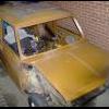
Right so I'm studying motorsport engineering at college and part of the course we have been taskede to build a gravity racer Now we are given this chassis and obviously have to build it up for race day.
this is ours
we decided that it was best to work from the frong to the back, so we set about making the suspension/steering assembly. When my team sat down to discuss what we were going to do about the suspension/steering, we decided that it wouldnt be worth running wishbone suspension due to the complexity of it all, so we have decided to copy the setup used by the kettler pedal cars.
(excuse the dodgey paint drawing :L)
this is currently getting remade with a longer end piece as like u can see, we didnt have any steering lock with the current setup
So the black bit is a C shaped hub as u can see, The red bit is a solid bar that runs across the length of the chassis. the yellow piece is a piece of threaded bar (just what we had to hand) that runs through the hub and the bar, this will allow the hub to turn. the orange bit is going to be a rubber washer to allow alittle bit of absorbation from any bumps or whatever we hit, and the brown bit will be a solid washer to keep the axle where it is. The grey bis is the wheel with the blue bit being the bolt that attaches the wheel to the hub. There will also be a lug welded to the side of the hub to connect the steering rods to to obviously allow us to steer :L
Now after designing that we thaught it would be a good idea to add a spanner to the works in the shape of some ride height adjustment brackets
Now the original plan was to weld these to the chassis, but if we were to do that, we had to be sure that they were welded perfectly straight or it wouldnt work. So instead, we decided to bolt them to the chassis instead
But ofcourse this wasnt without its drawbacks either as you all know and could work out, but doing this it would mean the axle could move side to side if we did hit a bump, bit like axle tramp to put it into car related terms :L so again, back to the drawing board.
Instead of redesigning it all, some clever cloggs (that being me) came up with the idea of adding some triangulation brackets to the height adjusters and then bolt them (or weld them) to the axle, thus decreasing the chances of axle tramp
Whilst all this axle work was going on, another member of the team set about making a steering wheel for the racer, so heres the results of his hard work
So thats about all we have done at the moment and considering we only have 2 and a half hours a week to do stuff and have to share a workshop with young kids, its a good achievement me thinks
Any feedback would be greatly appreciated and noted for use in further manafacture and development
Nick
College Gravity Racer Project
Started by
minidream94
, Nov 10 2011 07:49 PM
3 replies to this topic
#1
Posted 10 November 2011 - 07:49 PM
#2
Posted 27 November 2011 - 08:58 PM
i so wish i could have done somthing like this! gnvq art and design and hnd electronic graphics hasnt been of much use as a welder/mechanic
#3
Posted 29 November 2011 - 11:26 PM
This brings back memories! Back in my uni days our group project was to design a gravity racer with the help of a guy who had been building racers with local schools. He ran with Vauxhall sponsorship when they used to do gravity racing at the Goodwood Festival of Speed. His name escapes me at the moment, however he was promoting the building of gravity racers in schools and colleges and organising races. Your chassis looks VERY similar to the one he was working with so I wonder if its the same group that you're involved with? He was on The Gadget Show on channel 5 as well a while back, you can see some others members of our design team loitering in the background (I didn't go though...). We had a couple of trips to Brooklands to see a race he organised, the last time with the car we'd designed (I wonder where that is now?)
The important things were to make it as heavy as you can (more potential energy at the top of the hill = more speed at the bottom), keep centre of gravity low and minimise the amount of energy wasted as you move. Look at the wheel bearings and tyre rolling resistance first off, although we also spent some time in the wind tunnel looking at aerodynamics as we were aiming for high speeds (50mph+).
I wouldn't underestimate the importance of having some suspension, the tracks aren't always that smooth and having something that handles well gives you a bit more confidence in driving it. Is there enough room for the drivers feet with the beam axle in there? I can remember it all being a tight squeeze in that region to get feet and suspension bits packaged in.
Be interested to see how you get on, I might have to see if I can find any pictures and the like of ours
#4
Posted 30 November 2011 - 08:16 PM
nice:) at college we do projects and one of the choices was to do a gravity racer, we chose to restore a rubber bumper MGB and fit a 4L v8 landrover engine into it shoudl be fu!
good luck with your build! looks like its going to be alot of fun!
1 user(s) are reading this topic
0 members, 1 guests, 0 anonymous users