Well, it's just been Easter, so let's talk hatching. Or, in this case, hatch glass. Shaun came over yesterday and assisted me with getting the rear hatch glass down from the rafters. It IS a job I could have done by myself, but not without significant risk to the glass and/or myself. Given that the Midas rear hatch was made for just them, and Midas hasn't been around for decades, the likelihood of getting another was between slim and none, and Slim's on a plane to the Caribbean.
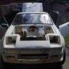
One thing I have established is that when you spray a car, no matter how well you THINK you've covered everything, you haven't. Not only was the hatch glass incredibly dirty, it also had orange overspray on it. Where on Earth could that have come from? (hides face in an "It wasn't me guv" kind of way). First thing's first - get it cleaned. Apologies for the lack of photos here - some idiot hadn't put the memory card back in the camera, so although I took about 5 photos, they did not save anywhere. Because that idiot was me... After washing off several years' worth of grime, which turned the water a hideous shade of grey-brown, Shaun and I set about removing the overspray with blades. This took us the best part of hour, but it was worth it. Although the hatch had some scratches, as you'd expect from a 44 year old piece of glass, it looked in pretty good nick. After giving it a full wipe down with glass cleaner, it was ready to be used.
I suddenly realised that I had not painted the other circular mounts which attach the glass to the hatch struts and hinges, so I found them in the box where I thought they were, rubbed them down and gave them a coat of primer and satin black. I also needed new rubber "gaskets", as I only had 2 - the others had disintegrated. Using the old ones as a template, I made six more from my sheet of rubber. They aren't perfect, but they're underneath mounts, will do the job required, and are in no way aesthetic, so I am happy with that!
I dove into my bag of seals and retrieved the hatch seal, all 2.9 metres of it. I carefully pressed this into place on the lip, and cut it to fit (it was about 5 cm too long). Next up was fitting th hatch. I quickly realised that the hinges, which were already on the car, would need to be taken off again and attached to the glass - it would be nigh-on impossible for me to fit them otherwise, as I was on my own by then. Lining the hinges back up to fit back to the bodyshell was surprisingly easy, even for someone like me who seems to be able to easily mess things up! I left the bolts a bit loose so I could lines the hatch up correctly. It wasn't far out, but it did need a little bit of shuffling over.
Last thing was the handle and lock mechanism. Again, this was relatively easy to fit, at least until I tried to do the bolt up on the back of the lock barrel. Yup, the thread decided to strip. You couldn't make this up! I am nothing if not resourceful, so I carefully drilled it out to 4.5mm before running an M5 tap down, and cutting a M5 bolt down to suit. This has worked beautifully. The lock mechanism is now fitted, but because the hatch seal is so new, I need it to settle before attempting to close it fully. It does not line up yet, but I am pretty certain that this will come with time!
Bald man hiding behind reflective glass

Circular mounts painted

Rubber gaskets being created

And how they came out. A bit shonky, but functional all the same

2.9 metre seal (claps flippers)

Fitted to car and trimmed to size

Gah! Stripped thread! Nuts!

Look! Glass has been fitted!