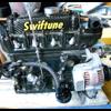
 500x_mini_cooper_cummins_v18.jpg 53.63K
59 downloads
500x_mini_cooper_cummins_v18.jpg 53.63K
59 downloadsMahooosive i know,
probably done for a demo and is not really attached to the mini, but it got me thinking what has been the largest engine ever fitted into a mini?


Speeding Along Now

Posted 21 December 2010 - 02:46 PM
500x_mini_cooper_cummins_v18.jpg 53.63K
59 downloadsThe Carbon Weezel
Posted 21 December 2010 - 03:05 PM
One Carb Or Two?
Posted 21 December 2010 - 04:44 PM
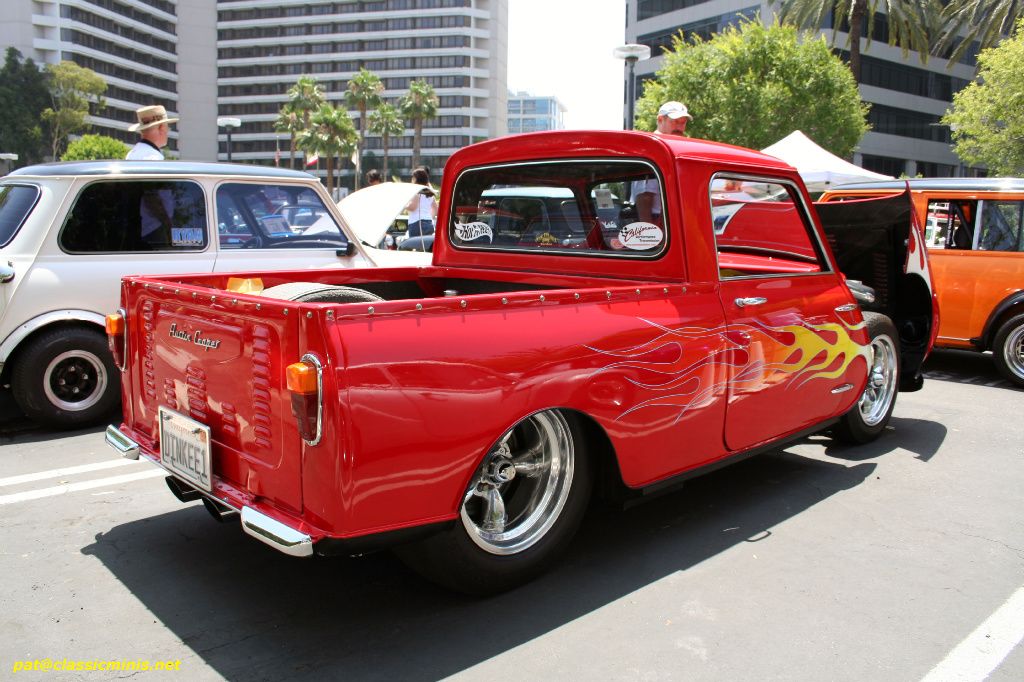
Just came across this image whilst bored on the net:
Mahooosive i know,
probably done for a demo and is not really attached to the mini, but it got me thinking what has been the largest engine ever fitted into a mini?

TMF fantasy F1 winner 2012

Posted 21 December 2010 - 04:51 PM


Mini Mad

Posted 21 December 2010 - 05:19 PM
Moved Into The Garage
Posted 21 December 2010 - 07:05 PM
 Pictures here:
Edited by mab01uk, 21 December 2010 - 07:19 PM.
Speeding Along Now
Posted 21 December 2010 - 09:39 PM
One Carb Or Two?

Posted 22 December 2010 - 12:15 AM
Stage One Kit Fitted

Posted 22 December 2010 - 01:35 AM
TMF fantasy F1 winner 2012
Posted 22 December 2010 - 09:50 PM

In the 1964 season Harry Ratcliffe of BRT had demonstrated with his Cooper Buick that when it came to low volume specialist cars, there was no such thing as bad publicity. The Cooper Buick had been a bit of a disaster from the start. A Mini with a 3.5 litre Buick V8 in the boot driving the front wheels through a special prop shaft and converted E type Jag axle in the front.
Harry described driving it at speed as being like trying to throw a sledge hammer shaft first. The strange thing was that the motoring press loved it. The Cooper Buick was featured in almost every major motoring publication of 1964 bringing some much needed publicity to the, at that time, little known northern outfit.
One Carb Or Two?

Posted 23 December 2010 - 12:20 AM
Crazy About Mini's
Posted 23 December 2010 - 01:35 AM
In the 1964 season Harry Ratcliffe of BRT had demonstrated with his Cooper Buick that when it came to low volume specialist cars, there was no such thing as bad publicity. The Cooper Buick had been a bit of a disaster from the start. A Mini with a 3.5 litre Buick V8 in the boot driving the front wheels through a special prop shaft and converted E type Jag axle in the front.
Harry described driving it at speed as being like trying to throw a sledge hammer shaft first. The strange thing was that the motoring press loved it. The Cooper Buick was featured in almost every major motoring publication of 1964 bringing some much needed publicity to the, at that time, little known northern outfit.


0 members, 1 guests, 0 anonymous users


