My Mk1 Mini Rebuild
#106

Posted 05 February 2013 - 09:55 PM
#107

Posted 07 February 2013 - 05:40 PM
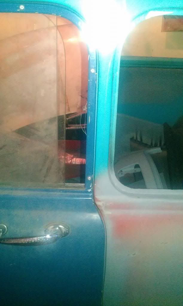
Also, clamped up wing and front panel to add a bit of structure whilst I was messing about with the door:
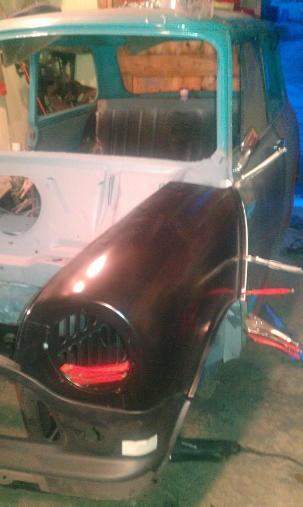
Applied the
Cheers
Edited by minimikej, 07 February 2013 - 05:43 PM.
#108

Posted 21 February 2013 - 07:18 PM
I was just thinking, if you were worried the shell might be slightly bent have you checked the alignment of the subframes, or more accurately the subframe mounting holes? That should tell you if the shell was bent at all?
I've been doing mine recently, its alot of work to do thoroughly, its taken me days actually and thats with my dad helping but peace of mind and all. I have a detailed diagram with a lot of measurements on it. I could did it out if your interested. I've been using some very large calipers from work to strike arcs and find center lines, also the front suspension points where the top and bottom arms attach to the subby can be useful if you have a good subframe.
#109

Posted 21 February 2013 - 07:35 PM
#110

Posted 21 February 2013 - 10:36 PM
Hi, yeah that would be great if you could find it but if I'm being truthful I'm scared at what I might find, and then what I could do about it apart from cry. I removed the drivers side inner wing today, wish I'd done this side first, it still had enough of the A post internals left to have answered my earlier questions - reason I couldn't see how the inner wing was meant to join the A pillar on the passenger side was because there was nothing there! Previous restorer just didn't bother replacing whatever he chopped out. I'll post some pics when I can find my phone lead.Hi Mike,
I was just thinking, if you were worried the shell might be slightly bent have you checked the alignment of the subframes, or more accurately the subframe mounting holes? That should tell you if the shell was bent at all?
I've been doing mine recently, its alot of work to do thoroughly, its taken me days actually and thats with my dad helping but peace of mind and all. I have a detailed diagram with a lot of measurements on it. I could did it out if your interested. I've been using some very large calipers from work to strike arcs and find center lines, also the front suspension points where the top and bottom arms attach to the subby can be useful if you have a good subframe.
Cheers
#111

Posted 21 February 2013 - 11:08 PM
For a change, and to get a horrid job out the way I started on the driver's side inner wing.
First off, I took the new inner wing and shock mount reinforcement back home and spot welded them with my incredibly expensive but almost completely unusable spot welder ( it won't run off the genny down my garage and it needs more than 13 amps - wired it into the cooker circuit when the missus was out
Next removed the inner wing and carefully unpicked the (original, un-bollocksed) A post. Here you can see the original Inner wing and the wonderfully well protected - not - old inner A panel:
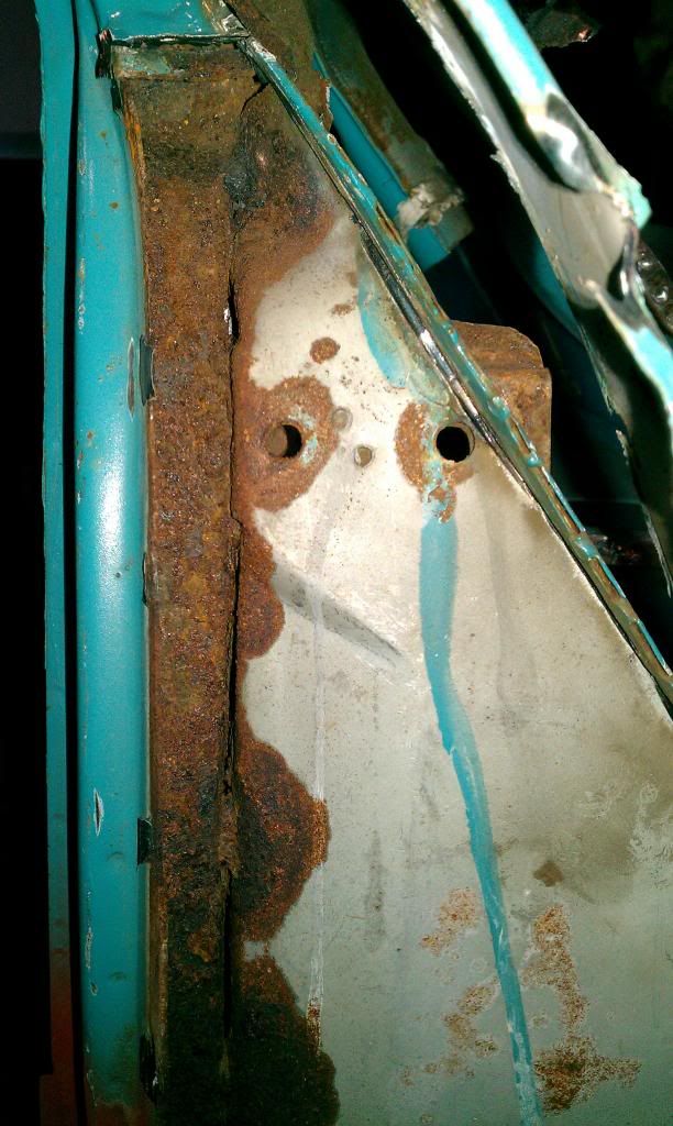
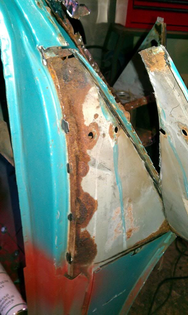
It did cross my mind that I could have put the doorsteps on the wrong side ! But clearly I'm not that daft as I'd left the M-Machine identifier on the panel - assuming they got it right :)
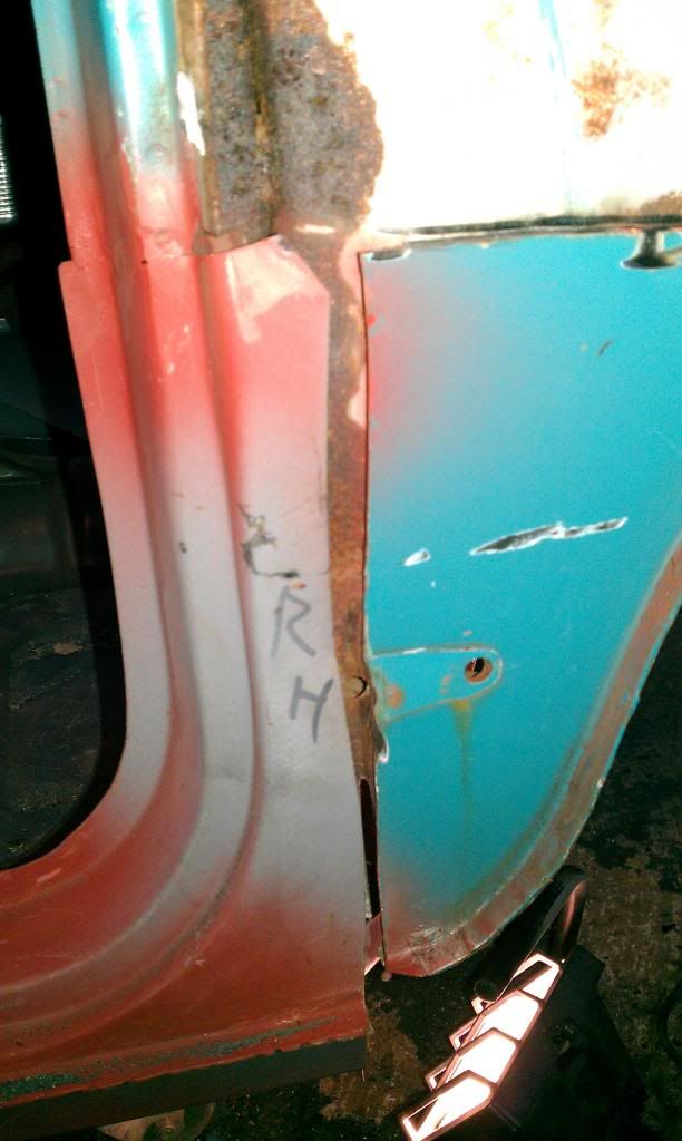
This side still had that foam plug at the top of the post that Lindsay Porter describes in the mini restoration bible. Internals have surface rust but the metal is so much thicker on the original panels! Will clean up best I can and Kurust.
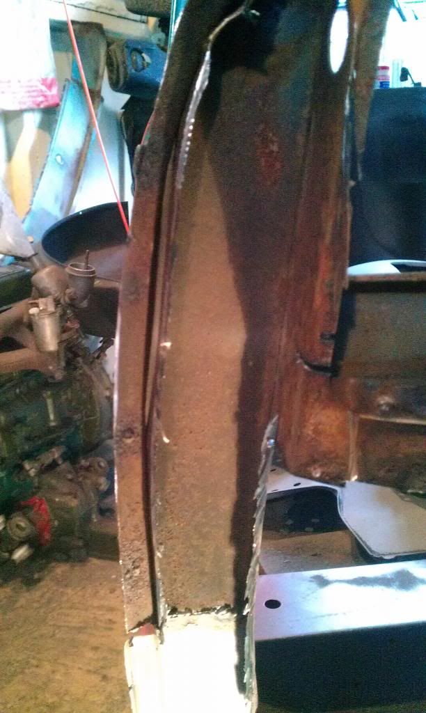
So that's most clutter out the way. Still need to linish and straighten out the spot weld flanges but the initial view is that the wing fits well. Also, there was no corrosion at all behind the shock mount (although it was full of sand for some reason)
Hope to progress some more tomorrow.
Cheers
#112

Posted 22 February 2013 - 12:12 AM
 subframe_alignment_dia.jpg 65.97K
36 downloads
 vertical_drop_dia.jpg 77.42K
34 downloads
vertical_drop_dia.jpg 77.42K
34 downloadsI'm not sure how much use the second pic is as I think its for later minis.
I found the subframe diagram really useful but it has no figures to relate front to back frames. I clamped a good quality long straight edge to the bottom of the front subframe perfectly in line with the top and bottom arm mounting positions, with the bare front subframe completely bolted into place I then measured back to the rear subframe mounts on the heelboard. Equal measurements both side gives you, hopefully parallels,equal diagonal measurements gives you square and eyed though front to back(2 long straight edges required, one on front subby, one in line with rear subframe heel board captive nuts) gives you true or parallel underneath.
I used large calipers for striking centers and negotiating the lumps and bumps of the underside of the car where straight edges dont work and made up some small jigs to save tape measure reader error on my part. I'm lucky as I have access to good quality measuring tools as its part of my job but a half decent level will serve as a pretty good straight edge. That, a tape measure and a little time should be enough.
I've just tacked the bottom of my car up and know its within less than 1mm between the suspension mounts but the upper body I'm sure is nowhere near that accurate but I don't think it matters as its just cosmetic really and more important the car drives in a straight line.
I deliberatly didn't use the rear subframe as its rubber mounted, I've only got a non gen one as well and its way out on the correct measurements according to that diagram.
Sorry for the waffle
#113

Posted 22 February 2013 - 12:20 AM
#114

Posted 22 February 2013 - 12:28 AM
#115

Posted 22 February 2013 - 11:07 AM
Maybe an admin could link to this in the FAQ section or something?
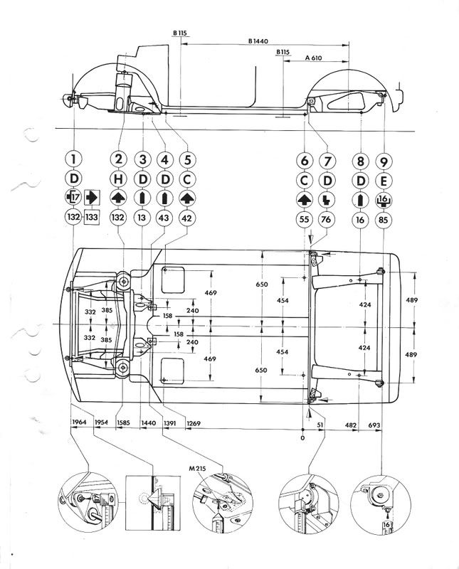
It describes all the weird bobbins that dangle from mounting points and stuff. When I sweep out the mountains of grinding dust and rust from the floor I will have a go at making plumbobs and drawing the reference points on the garage floor.
Hopefully will have some time today to carry on with the inner wing although it's blimmin cold up here and trying to snow.
Wish I had a garage with mains power, next time I will definitely work mostly with the spot welder. No contest for tidyness.. :-/
Cheers
Mike
#116

Posted 22 February 2013 - 03:39 PM
First thread I've read as a newbie and what a belt-er
#117

Posted 23 February 2013 - 10:34 AM
Well, I did get down to the garage yesterday to clean up the spot weld flanges and start fitting panels up.
I clamped the inner wing in place and then measured the wing top heights from the subframe. Drivers side was naturally about 4mm too high at the subframe tower.
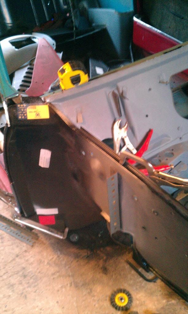
But by changing the clamping order I got it bang on, and then started drilling holes for spot welding.
And then this happened
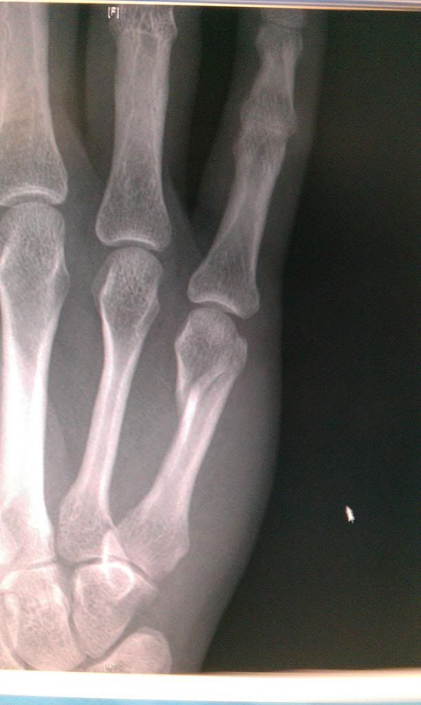
Sod it. The drill caught a rag I carelessly left under what I was drilling, and being a powerful thing whipped round and broke a metacarpal. Full lower arm cast. That's me out of action for the next 6 weeks
#118

Posted 23 February 2013 - 11:02 AM
#119

Posted 23 February 2013 - 01:20 PM
Sod it. The drill caught a rag I carelessly left under what I was drilling, and being a powerful thing whipped round and broke a metacarpal. Full lower arm cast. That's me out of action for the next 6 weeks
Ouch! Rags, gloves things which catch and rotating tools always end in disaster, one caught me out at work the other day despite going over it in my head every time I go near anything like that.
Wish you a speedy recovery pal, get back on the mini soon.
#120

Posted 23 February 2013 - 02:03 PM
Can you start to refurb parts or anything less manual?
2 user(s) are reading this topic
0 members, 2 guests, 0 anonymous users


