Hmm, as far as I know at the moment, I am going to use a bit of/or most of the toeboard and tunnel on the wagon/pup the middle of the crossmember bulkhead and the dash in the van and the inner wings I am not sure of yet, need to get the wagon up and stripped so I can figure that out. I still have that complete b pillar though that is unspoken for, And I might be smoothing out the saloon roof and modding it to replace the ribbed estate roof. I just don't know yet. I just know I need to get the nose broken down so I can bring the wagon home.
As for the 850, I's likely going to be hoisted up into the rafters filled with my early bits when our shop is built so as to get it out of the way for now.
Chris

1960 Morris 850 And Friends
Started by
CLM
, Aug 12 2010 01:20 AM
417 replies to this topic
#77

CLM
-
- Members
-

- 817 posts
One Carb Or Two?
Posted 16 August 2011 - 08:58 AM
This is not much of an update, but, I recived the subby mount bits from Smurf today, it only came with one rear mount, and as I figured I was going to make my own solid mounts I took my time today building this.
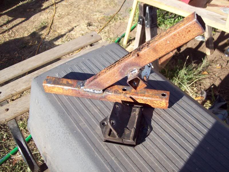
It was simply 3 pieces of inch square I drilled and fitted around the one mount I had so I could fabricate up a jig.
I don't have any suitable steel around to make a subframe mount from so I just rough cut a couple pieces and drilled them to test out the jig.
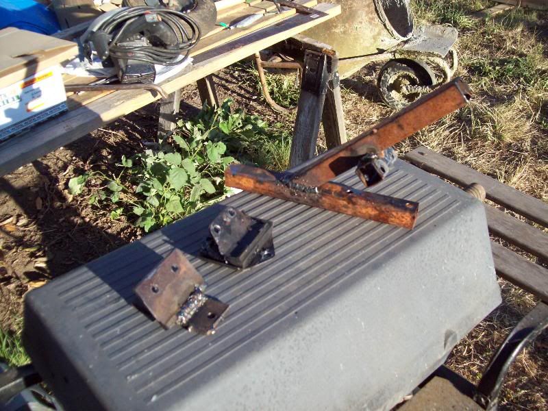
It seems to fit well, though I need to bevel the wide edges. At least I can use this for mocking up the subframe on the van now. I will probably make up a pattern for the two pieces of the solid mount for the next ones I make, and probably put some larger wire in my mig for some better penetration.
Need to do some repair work to the subframe before I can mount it... I am not going to post any pictures of it untill it's repaired... you bunch will call me nuts!
Chris
It was simply 3 pieces of inch square I drilled and fitted around the one mount I had so I could fabricate up a jig.
I don't have any suitable steel around to make a subframe mount from so I just rough cut a couple pieces and drilled them to test out the jig.
It seems to fit well, though I need to bevel the wide edges. At least I can use this for mocking up the subframe on the van now. I will probably make up a pattern for the two pieces of the solid mount for the next ones I make, and probably put some larger wire in my mig for some better penetration.
Need to do some repair work to the subframe before I can mount it... I am not going to post any pictures of it untill it's repaired... you bunch will call me nuts!
Chris
#78
minimuk
-
- Members
-
- 1,946 posts
Camshaft & Stage Two Head
- Location: Midlands
Posted 18 August 2011 - 09:42 PM
well,.. you are very brave indeed, excellent project,...2 yr plan? can you get parts and panels in the US? will look in now and then and checking on your progress, good luck!
#79
CLM
-
- Members
-
- 817 posts
One Carb Or Two?
Posted 19 August 2011 - 04:58 AM
Eh 2 year plan is to have at least 2 on the road lol Hope to have the van driveable by the end of the year, And have something that actually looks somewhat pickup-ish on the rack. Once I have enough of the pup completed for measurements I will start making a secret accessory for it and then plan to go traveling in it. Van is getting a Suzuki g10 engine and 5 speed box in it and pup a Mazda 1.3l with a 5 speed box (ford festiva/mazda 121/kia pride power unit.. very reliable)
Fitting out, The van is going to get late rover interior If I can manage it with a pressed grill and the yellow that it is, the pup will be a mk1 cooper replica in almond green and oew roof. And the 60 if it hasnt moved on will be restored back to oew with a repro fleck interior hopefully a 1100 if not it will be a 998 with magic wand.
And parts, not hard to get, just somewhat expensive for the skint. Most of the time it is cheaper to buy there and have shipped here if you have a sizeable order... Bed sides and whatnot will likely come that way.
Chris
#80
CLM
-
- Members
-
- 817 posts
One Carb Or Two?
Posted 27 August 2011 - 03:52 AM
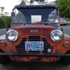
Hey all, small update, we are still building the shop so not alot done, Have made progress on my stupid secret project. So far I have turned This....
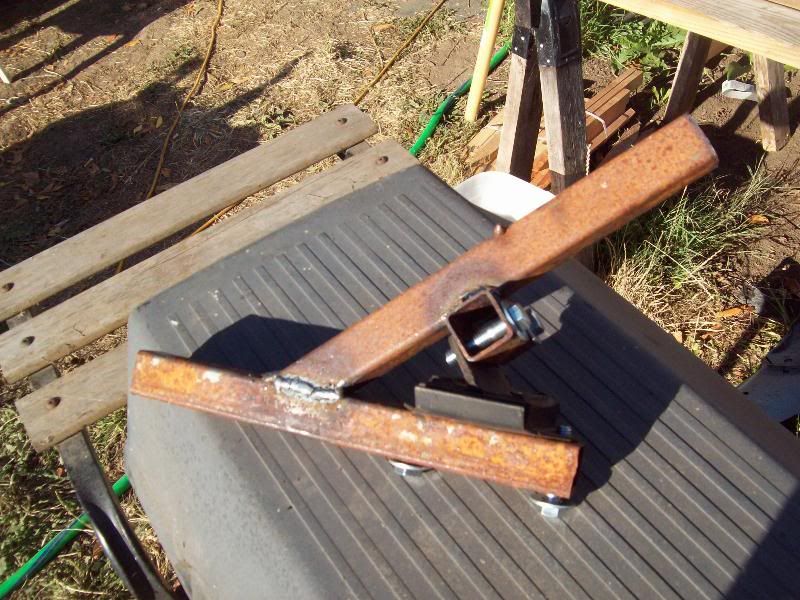
Into
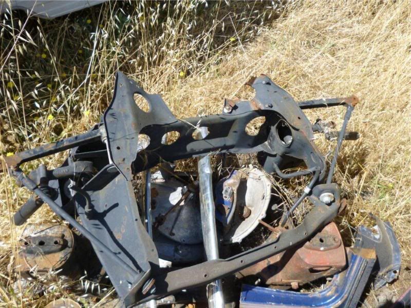
And angles and measurements are measuring up and square so far so I think it will be useable when I am done.
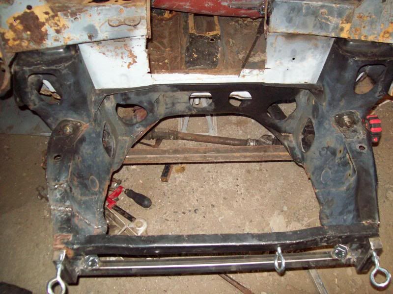
It's a late jap spec auto front subframe, the condition of the bearings and cones were in great shape, the subby however was in a shape more befitting a pretzle. First thing I did after getting it home... Actually I think I should make this statement.
I Got this for free when I bought a mk1 solid mount front subframe that has a rusty rubber cone locator ring in one tower. It was ment to be the donor for the spring mount to go into the mk1 subframe. I however had the rubber frame that was chopped up that I can get the spring mount out of so there was no harm trying to straighten this. I will be using this subframe to mount a subaru/geo g10 3 cyl 5speed 1.0 engine so much of the damaged area on the right side will be cut out and reformed with new steel to make room for the front pully of the g10 power unit... Now where were we? Oh yeah.
First thing I did to it after getting it home was to pull out the grinder with a 1mm cutting disk and cut right through the center of the big folds in the metal so I was only needing to straighten one section at a time and would not be fighting the folds. Once I had done that I used a long bar and some eye bolts to pull the front bar back to where it should be (and a little too far, had to do some unbending) Aslo bent some of the engine mount area back and then the shop became a priority so It got set off to the side.
A week later I started working on the mangled rear mount some, I make up a template from the left side to set the slice to where it should be and welded it up and set the frame aside, this is when I went and made that silid mount earlier.
During my free time after that I used the mk1 subby to make up a frame jig locating the suspension arm mounts to the front mounts out of inch square tuping and angle iron to which I forced the bent subby onto and bolted it to the van. Using a series of long poles and strategic bracing IO worked on the tweaked areas to get it in as close to original shape as I could and to the point it is in the pictures.
At this point I need to pick up some steel plate in a compareable thickness to this subframe and make a couple patches, but at this point it measures out as square.
Some more pictures at
http://s1202.photobucket.com/albums/bb374/clm1977/mini%20van/subframe/
Chris
Into
And angles and measurements are measuring up and square so far so I think it will be useable when I am done.
It's a late jap spec auto front subframe, the condition of the bearings and cones were in great shape, the subby however was in a shape more befitting a pretzle. First thing I did after getting it home... Actually I think I should make this statement.
I Got this for free when I bought a mk1 solid mount front subframe that has a rusty rubber cone locator ring in one tower. It was ment to be the donor for the spring mount to go into the mk1 subframe. I however had the rubber frame that was chopped up that I can get the spring mount out of so there was no harm trying to straighten this. I will be using this subframe to mount a subaru/geo g10 3 cyl 5speed 1.0 engine so much of the damaged area on the right side will be cut out and reformed with new steel to make room for the front pully of the g10 power unit... Now where were we? Oh yeah.
First thing I did to it after getting it home was to pull out the grinder with a 1mm cutting disk and cut right through the center of the big folds in the metal so I was only needing to straighten one section at a time and would not be fighting the folds. Once I had done that I used a long bar and some eye bolts to pull the front bar back to where it should be (and a little too far, had to do some unbending) Aslo bent some of the engine mount area back and then the shop became a priority so It got set off to the side.
A week later I started working on the mangled rear mount some, I make up a template from the left side to set the slice to where it should be and welded it up and set the frame aside, this is when I went and made that silid mount earlier.
During my free time after that I used the mk1 subby to make up a frame jig locating the suspension arm mounts to the front mounts out of inch square tuping and angle iron to which I forced the bent subby onto and bolted it to the van. Using a series of long poles and strategic bracing IO worked on the tweaked areas to get it in as close to original shape as I could and to the point it is in the pictures.
At this point I need to pick up some steel plate in a compareable thickness to this subframe and make a couple patches, but at this point it measures out as square.
Some more pictures at
http://s1202.photobucket.com/albums/bb374/clm1977/mini%20van/subframe/
Chris
#81
johnsn
-

- Just Joined
-
- 69 posts
Stage One Kit Fitted
- Local Club: OMS
Posted 27 August 2011 - 02:53 PM
Good work!
I love reading this thread.
Keep that jig. If you add to it so you can bolt a sub frame in it with all the mounting bolts,you can use it to check and straighten sub frames, and mod them to fit other engines and transmissions.
You said "subaru/geo g10 3 cyl 5speed 1.0 engine".
Do you mean Suzuki/geo g10 3 cyl 5speed 1.0 engine.
Or Subaru/Justy 3 cyl 5speed 1.x engine?
I have the Suzuki parts, and a sub frame I'm making fit.
I cut up the sub frame more than needed because it was bent. I don't know why I didn't think of straightening it.
The only issue I saw so far is the diff of the trans hits the the rack where the pinion goes in it.
Some judicious grinding on the trans and rack should sort that out.
But with my too many projects, I haven't got back to it.
Keep up the good work. and keep posting.
I'm still trying to make time to come down to see you, but I have to get my place cleaned up, or my wife will be unhappy , to put it mildly
  , and get my stuff so the rain wont ruin it.
john
I love reading this thread.
Keep that jig. If you add to it so you can bolt a sub frame in it with all the mounting bolts,you can use it to check and straighten sub frames, and mod them to fit other engines and transmissions.
You said "subaru/geo g10 3 cyl 5speed 1.0 engine".
Do you mean Suzuki/geo g10 3 cyl 5speed 1.0 engine.
Or Subaru/Justy 3 cyl 5speed 1.x engine?
I have the Suzuki parts, and a sub frame I'm making fit.
I cut up the sub frame more than needed because it was bent. I don't know why I didn't think of straightening it.
The only issue I saw so far is the diff of the trans hits the the rack where the pinion goes in it.
Some judicious grinding on the trans and rack should sort that out.
But with my too many projects, I haven't got back to it.
Keep up the good work. and keep posting.
I'm still trying to make time to come down to see you, but I have to get my place cleaned up, or my wife will be unhappy
, to put it mildly , and get my stuff so the rain wont ruin it.john
#82
CLM
-
- Members
-
- 817 posts
One Carb Or Two?
Posted 27 August 2011 - 08:33 PM
Oops yeah Suzuki/geo like the post above it says heh.
I was planning on adding other mounting points, but for this it sort of needed to be a bolt on the bottom type so I could use it with the subframe bolted to the van.
Should post some pics of your projects John
Chris
I was planning on adding other mounting points, but for this it sort of needed to be a bolt on the bottom type so I could use it with the subframe bolted to the van.
Should post some pics of your projects John
Chris
#83
CLM
-
- Members
-
- 817 posts
One Carb Or Two?
Posted 28 August 2011 - 05:32 AM
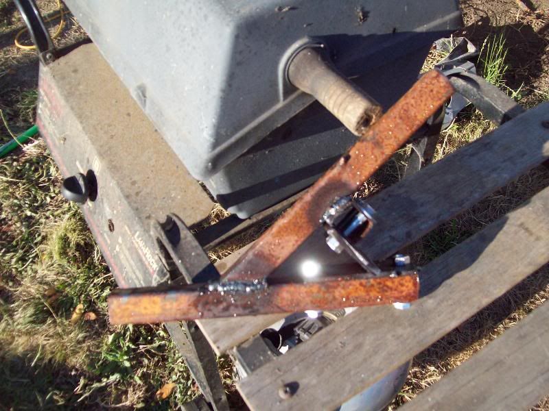
A bit of welding on the subframe today,
Chris
Chris
#84
johnsn
-
- Just Joined
-
- 69 posts
Stage One Kit Fitted
- Local Club: OMS
Posted 17 September 2011 - 12:49 AM
Yes,I should post some pics of your projects, but I don't know if it goes in Mini based, or other.Oops yeah Suzuki/geo like the post above it says heh.
I was planning on adding other mounting points, but for this it sort of needed to be a bolt on the bottom type so I could use it with the subframe bolted to the van.
Should post some pics of your projects John
Chris
john
#85
CLM
-
- Members
-
- 817 posts
One Carb Or Two?
Posted 17 September 2011 - 03:00 AM
Well the engine part may not, but it is still a complete mini rebuild I imagineYes,I should post some pics of your projects, but I don't know if it goes in Mini based, or other.
Oops yeah Suzuki/geo like the post above it says heh.
I was planning on adding other mounting points, but for this it sort of needed to be a bolt on the bottom type so I could use it with the subframe bolted to the van.
Should post some pics of your projects John
Chris
john
I have 2 non-mini engine projects in here, though most of the work on them is still mini related. Body work, paint suspension so I still think they count hehe.Chris
#86
CLM
-
- Members
-
- 817 posts
One Carb Or Two?
Posted 17 September 2011 - 04:44 AM
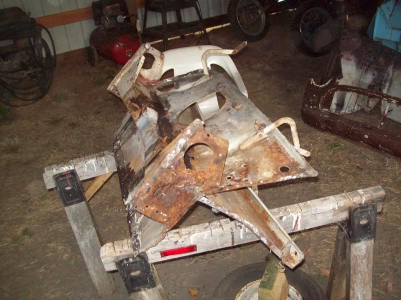
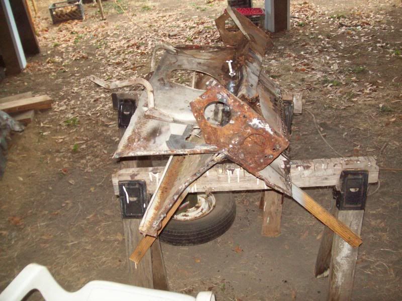
Hey john,
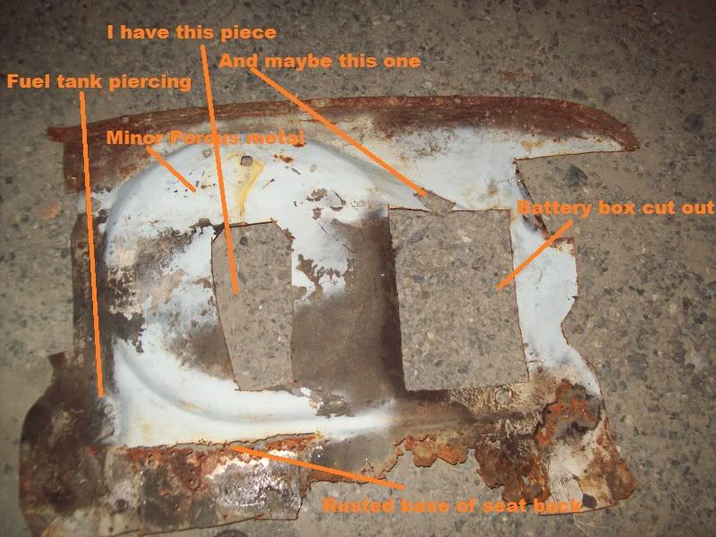
The shape of the spare well is there and intact, I believe that was what you were needing. It's slightly porous towards the bumper side of the spare well, but most of it is solid.
Chris
The shape of the spare well is there and intact, I believe that was what you were needing. It's slightly porous towards the bumper side of the spare well, but most of it is solid.
Chris
#87
johnsn
-
- Just Joined
-
- 69 posts
Stage One Kit Fitted
- Local Club: OMS
Posted 20 September 2011 - 08:23 PM
Oh Boy Oh Boy Oh Boy.Hey john,
The shape of the spare well is there and intact, I believe that was what you were needing. It's slightly porous towards the bumper side of the spare well, but most of it is solid.
Chris
That will work.
I can rebuild it.

Got to go.
john
#88
CLM
-
- Members
-
- 817 posts
One Carb Or Two?
Posted 21 September 2011 - 09:45 AM
We are heading back up to Vancouver Washington in about 3 weeks perhaps, I should see if I can get it the b panel and the bulkhead ready.
Chris
Chris
#89
johnsn
-
- Just Joined
-
- 69 posts
Stage One Kit Fitted
- Local Club: OMS
Posted 23 September 2011 - 08:58 PM
That's fine.
Gives me time to get the 1100 short block off the transmission. I found it way in the back of the garage.
john
Gives me time to get the 1100 short block off the transmission. I found it way in the back of the garage.
john
#90
CLM
-
- Members
-
- 817 posts
One Carb Or Two?
Posted 01 October 2011 - 08:29 AM
Been busy dismantling a motorhome and other stuff, and with no lights in the shop it does tend to get dark, but I have dismantled that mini shell some more, I managed to get the other wing off, it's in a bit worse shape, but still complete so I can rebuild it as needed.
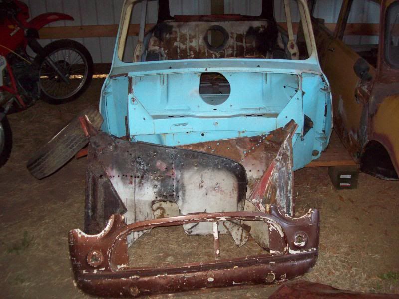
After the other inner wing was off I took the toeboard loose from the firewall, that turned out to be the easiest job so far, a few spot welds and it fell off.
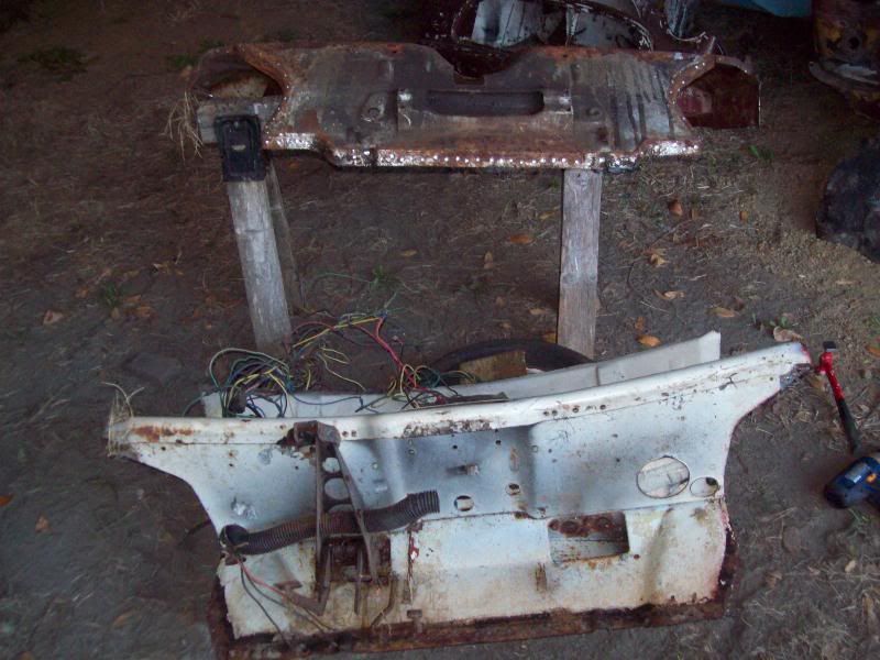
After it was off I stripped it down taking off all the items I had neglected to take off to this point and worked at determining how to remove the parcel shelf which proved a bit tricky.
I finally decided how best to get it off would entail damaging it slightly, I drilled out the 6 spotwelds that are above the line of the front crossmember and gently folded it down so I could get to the spot welds from the dash side as they are different from the crossmember spot welds and then had the dash off in short order.
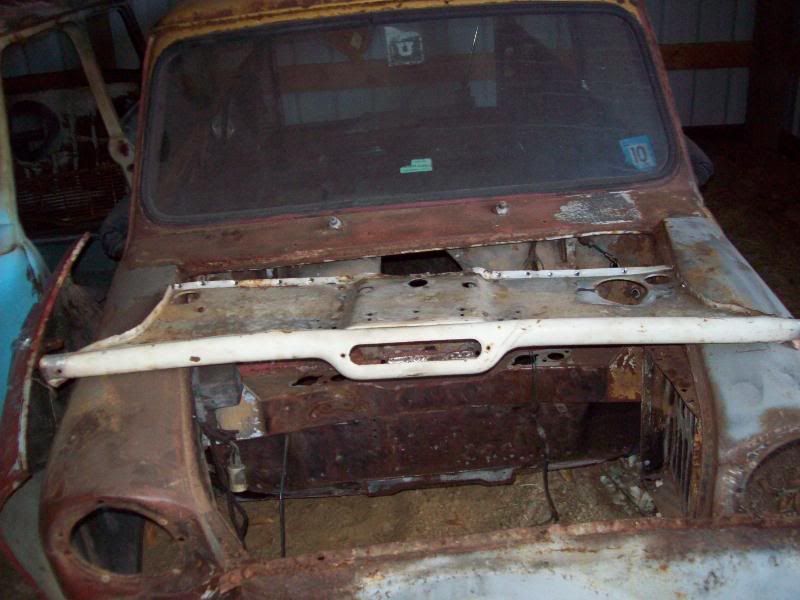
It is in somewhat rough shape, but it's far better then the dash in the van that has the whole center chopped out. I would rather a more correct dash in the van, but this is what I have heh.
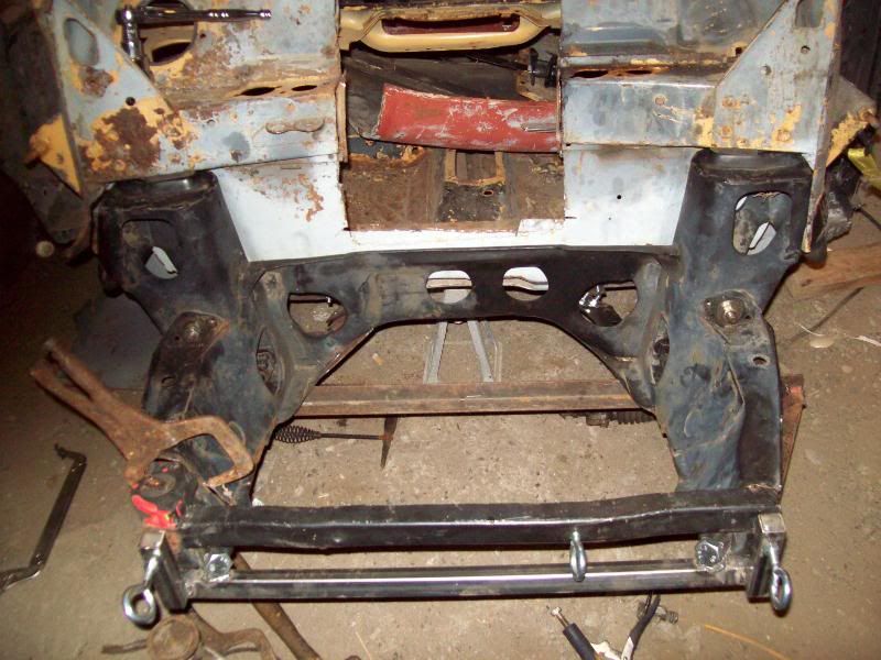
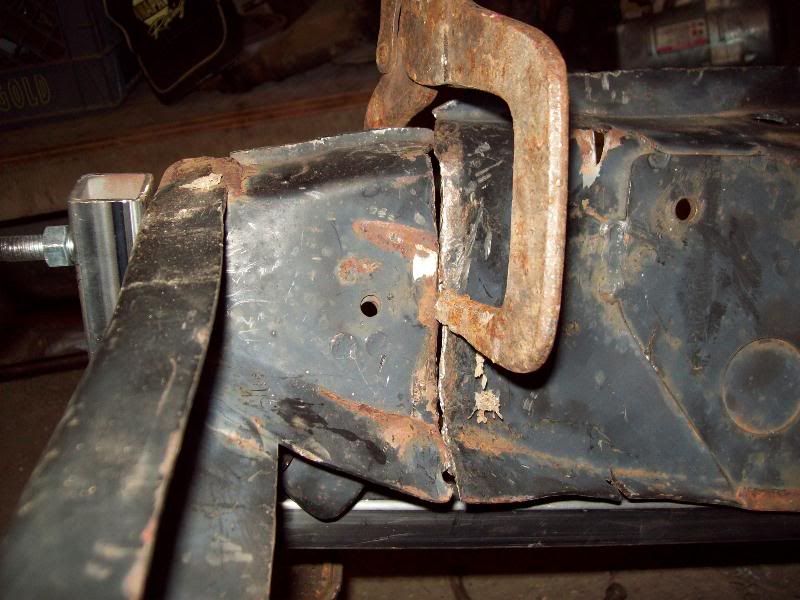
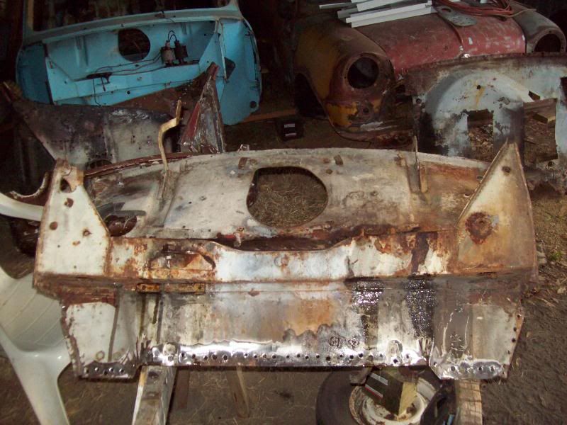
That left me with the bulkhead and the crossmember, I marked out the areas I am going to need to cut for the van to get your thoughts on it John.
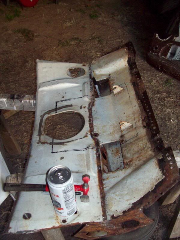
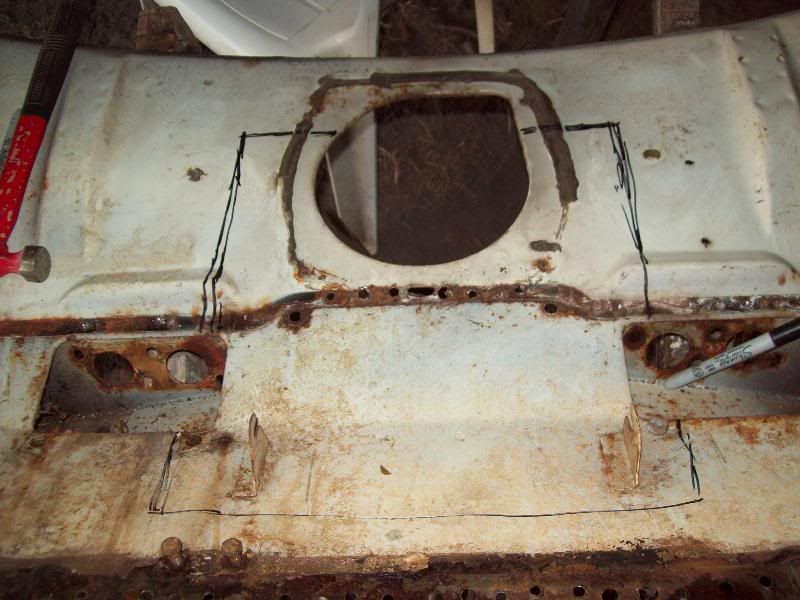
I should cut it right to the bottom of it for the van, but that will leave the remaining pieces somewhat flimsy. If I cut them off before removing the crossmember however I should be able to put some sheet back in there if you would like. I'm not sure, so havent cut anything yet.
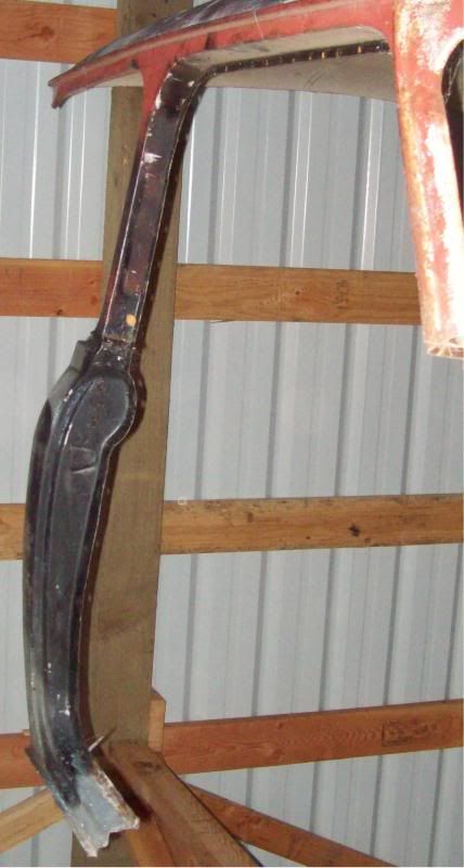
Oh, and here's that b-pillar.
Chris
After the other inner wing was off I took the toeboard loose from the firewall, that turned out to be the easiest job so far, a few spot welds and it fell off.
After it was off I stripped it down taking off all the items I had neglected to take off to this point and worked at determining how to remove the parcel shelf which proved a bit tricky.
I finally decided how best to get it off would entail damaging it slightly, I drilled out the 6 spotwelds that are above the line of the front crossmember and gently folded it down so I could get to the spot welds from the dash side as they are different from the crossmember spot welds and then had the dash off in short order.
It is in somewhat rough shape, but it's far better then the dash in the van that has the whole center chopped out. I would rather a more correct dash in the van, but this is what I have heh.
That left me with the bulkhead and the crossmember, I marked out the areas I am going to need to cut for the van to get your thoughts on it John.
I should cut it right to the bottom of it for the van, but that will leave the remaining pieces somewhat flimsy. If I cut them off before removing the crossmember however I should be able to put some sheet back in there if you would like. I'm not sure, so havent cut anything yet.
Oh, and here's that b-pillar.
Chris


1 user(s) are reading this topic
0 members, 1 guests, 0 anonymous users


