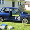


I have a 78/79 1275GT (not 100% which) that I am doing a bare shell restoration of.
It has a diagonal split braking system with the GMC167 master cylinder and no brake booster. I've just bought an Automec brake line kit from Minispares to put on (and Goodridge braided lines). I've been laying them out trying to figure out which piece goes where, and I'm pretty sure I've got it sorted (using the Automec information, and the original brake line diagram from MiniMania etc), however I'm not totally convinced...hopefully someone can help!
Firstly the lengths of pipe don't match those from the original MiniMania diagram, some of them are a few inches out etc. My shell is in the paint bay at the moment so I can't check that they're going to reach. Are they shorter due to the fact they're easier to bend that the original piping so can therefore take a more 'direct' route between joins?
Secondly, every connection is metric except for 2 and I can't understand why. One of them is a UNF male on the end of the long piece going from front to rear (the end that connects to the 3 way on the bulkhead), and the other is a UNF male on the end of the piece between the front braided line and 3 way. The same pipes on the other side of the car are metric, so why are these different??
The kit gives me 2 pieces to choose from to go between the master cylinder and 3 way on this side-
UNF male to UNF male, or
metric male to metric male.
Since the master cylinder is metric I obviously have to use the metric ended one. This makes for 2 UNF and 1 metric male ends connecting to the 3way. I'm not sure if they even make these? Regardless, it seems really strange that there should be these 2 UNF connections....any idea why?
Please someone enlighten me

Thanks
- Dan