Rev Counter Not Working
#1

Posted 03 November 2009 - 12:59 PM
Year:1989
Description of problem (please be as in depth as possible):
Rev counter just stopped working after i changed the speedo cable, any pointers?, is it just coincidence that it has stopped when i have changed the speedo cable?
Any non-standard parts that might be involved with the problem?
#2

Posted 03 November 2009 - 02:28 PM
#3

Posted 03 November 2009 - 03:01 PM
#4

Posted 03 November 2009 - 06:19 PM
Not really; the tacho works of fly-leads, not the printed curcuit board (pcb). The tacho only requires two feeds (light green with orange tracer, and white with black tracer) - should be one space connector and one bullet on yours.i have noticed a rip in the printed circuit board on the back of the rev counter, can this cause the problem?
If the wires are connected at the gauge, check the ligt green with orange wire is connected ok to the fuse box - should be on the thrid fuse down on the bulkhead. The white with black goes to the coil, this could also be a dodgy connection.
HTH
Ryan
Edited by L400RAS, 03 November 2009 - 06:22 PM.
#5

Posted 03 November 2009 - 06:21 PM
Not really; the tacho only requires two feeds - should be one space connector and one bullet on yours.i have noticed a rip in the printed circuit board on the back of the rev counter, can this cause the problem?
Ryan
Does it not also need an earth as well that it gets from the printed circuit board - I know mine did??
#6

Posted 03 November 2009 - 09:12 PM
#7

Posted 05 November 2009 - 10:38 AM
#8

Posted 05 November 2009 - 12:00 PM
I will bheck it out tommorow, i am guna replace the pcb anyway because it has caused the lights to stop working behind the dash.Will let ya kno how i get on
The pcb is faily easy to repair; I did mine by just cleaning off the laquer either side of the break exposng the copper (this can be done with fine emery paper) then solder a piece of wire across the gap. If you want to make a good, none corrodable job of it paint a coat of nail varnish over the finished joint.
Dave.
#9

Posted 05 November 2009 - 12:17 PM
Phil
#10

Posted 05 November 2009 - 01:24 PM
Use a lowish wattage soldering iron, 15w is ideal, 25w max. Do not use one of the 'instant heat' gun types nor heaven forbid, a blowlamp. Otherwise you will overheat the copper and it will curl-up and peel off the 'plastic' board.
Before you put it all back together it's worth cleaning all the exposed copper connection points i.e. around where the bulb holders, the earthing screws and the multi-plug all make their contacts. This is best done with 'Scotch Cloth' (the rough side of a washng-up sponge).
Be careful when you tighten the earthing screws as this can 'twist' the circuit board putting stress on it which will cause future breakdown.
Edited by MINY, 05 November 2009 - 01:28 PM.
#11

Posted 03 March 2010 - 05:59 PM
I will bheck it out tommorow, i am guna replace the pcb anyway because it has caused the lights to stop working behind the dash.Will let ya kno how i get on
The pcb is faily easy to repair; I did mine by just cleaning off the laquer either side of the break exposng the copper (this can be done with fine emery paper) then solder a piece of wire across the gap. If you want to make a good, none corrodable job of it paint a coat of nail varnish over the finished joint.
Dave.
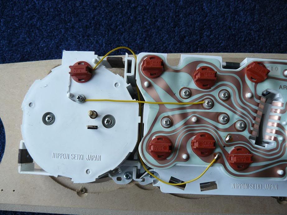
Sorry to revive a pretty-much dead thread, but I want to separate my three clock dials (move rev counter and speedo ect). However, the PCB needs to be attached.
If I am right, the PCB is just a neater way of connecting everything up rather than using wires - if so, would it be possible to cut the 3 dials, leaving sections of the PCB attached to the respective dials, and then "repair" the cuts by reconnecting the PCB bits with wire?
I'm asking you Min E because it sounds like you know what your on about!
#12

Posted 03 March 2010 - 10:30 PM
I will bheck it out tommorow, i am guna replace the pcb anyway because it has caused the lights to stop working behind the dash.Will let ya kno how i get on
The pcb is faily easy to repair; I did mine by just cleaning off the laquer either side of the break exposng the copper (this can be done with fine emery paper) then solder a piece of wire across the gap. If you want to make a good, none corrodable job of it paint a coat of nail varnish over the finished joint.
Dave.
Sorry to revive a pretty-much dead thread, but I want to separate my three clock dials (move rev counter and speedo ect). However, the PCB needs to be attached.
If I am right, the PCB is just a neater way of connecting everything up rather than using wires - if so, would it be possible to cut the 3 dials, leaving sections of the PCB attached to the respective dials, and then "repair" the cuts by reconnecting the PCB bits with wire?
I'm asking you Min E because it sounds like you know what your on about!
no reason why not, here's mine. I had two clocks and fitted the third with wires....

#13

Posted 03 March 2010 - 10:58 PM
I will bheck it out tommorow, i am guna replace the pcb anyway because it has caused the lights to stop working behind the dash.Will let ya kno how i get on
The pcb is faily easy to repair; I did mine by just cleaning off the laquer either side of the break exposng the copper (this can be done with fine emery paper) then solder a piece of wire across the gap. If you want to make a good, none corrodable job of it paint a coat of nail varnish over the finished joint.
Dave.
Sorry to revive a pretty-much dead thread, but I want to separate my three clock dials (move rev counter and speedo ect). However, the PCB needs to be attached.
If I am right, the PCB is just a neater way of connecting everything up rather than using wires - if so, would it be possible to cut the 3 dials, leaving sections of the PCB attached to the respective dials, and then "repair" the cuts by reconnecting the PCB bits with wire?
I'm asking you Min E because it sounds like you know what your on about!
no reason why not, here's mine. I had two clocks and fitted the third with wires....
And all works well?
And thanks for picture - robtheplod, you are a star!
1 user(s) are reading this topic
0 members, 1 guests, 0 anonymous users


