The dedication to detail is quality! some very good builds being showcased on here, awaiting further updates over Winter!!


'busavan
Started by
rustandoil
, Aug 18 2009 10:29 AM
92 replies to this topic
#62

sonikk4
-
- Admin
-

- 16,033 posts
Twisted Paint Polisher!!!
- Name: Neil
- Location: Oxfordshire
Posted 23 November 2011 - 09:49 PM
Loving all of the machined parts and the way you approach things. Ohh for access to a lathe and milling machine.
#63
rustandoil
-
- Members
-
- 317 posts
Speeding Along Now
- Location: Gloucestershire
Posted 24 November 2011 - 04:30 PM
Thanks for the comments, have to admit being lucky with access to tool-room equipment and now a CNC mill  what with the people i come into contact with there aint much i cant get machined
There is a small update to the thread that i am working on, nothing much, just the way i have done the coolant pipes and other pipework .
.
what with the people i come into contact with there aint much i cant get machined There is a small update to the thread that i am working on, nothing much, just the way i have done the coolant pipes and other pipework
.
Edited by rustandoil, 24 November 2011 - 04:31 PM.
#64
crispy
-

- Noobies
-
- 38 posts
On The Road
Posted 24 November 2011 - 08:05 PM
You guys do some great work machining! Those throttle cable ends are a nice touch!
#65
rustandoil
-
- Members
-
- 317 posts
Speeding Along Now
- Location: Gloucestershire
Posted 04 December 2011 - 08:32 AM
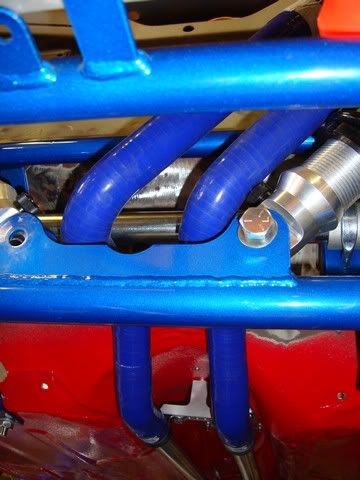
I mounted the radiator to see what needed to be done to connect the coolant pipes, i couldn't figure how the stuff i got from Z-Cars was supposed to work  so my fix was a trip to Silicon hoses (luckily only half an hour away) to purchase four 45 degree bends and some alloy joiners.
After a lot of careful measuring and cutting i am very pleased with the result wont be quite so tidy when its got hose clips on
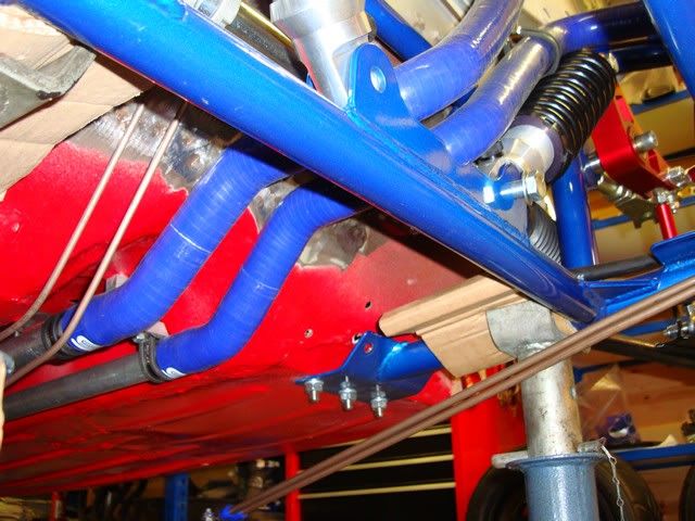
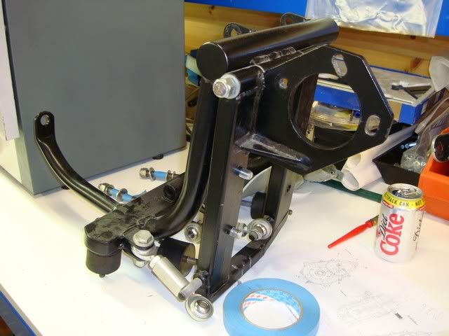
I mounted the servo so i could get the brake pipes sorted out, also the clutch reservoir on a alloy bracket, i have chosen to use copper nickel from front to rear, probably not my best decision as i don't really find it too easy to work with and has caused a few headaches
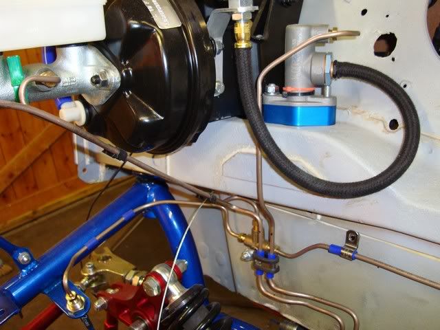
Because of the decision to use copper nickel pipes i found it was going to be very difficult to get them in the tunnel particularly where they have to exit around the frame at the rear, so i have decided to run them along the underside of the floor, not what i really wanted but if secured with some nice clamps i am sure they will be fine.
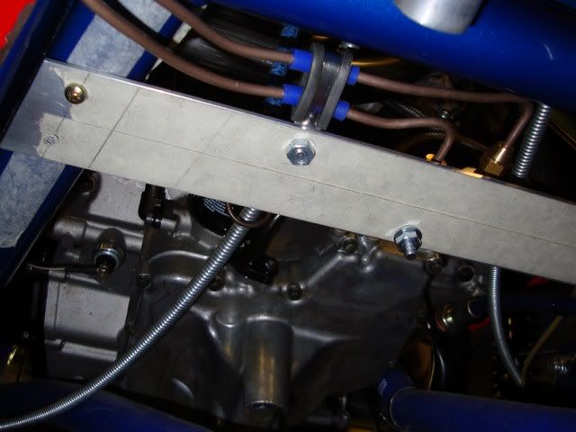
I have designed the pipe clamps and had my toolmaker (thanks Bri) make up one to see how its going to work, seems ok just need a gap in the paid w ork so we can make stuff for the van
All well and good but i am worried that i may have a clash of mounting points with my seat mounting so i have now ordered seats which will be fixed in place the i can see where i can fix the pipes.
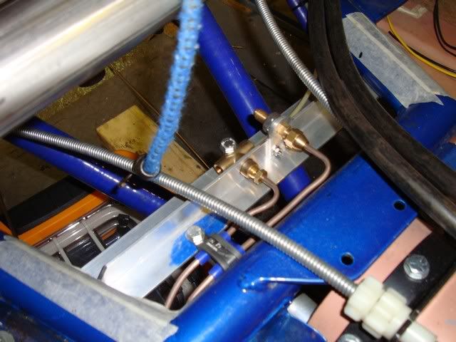
The rigid pipes terminate at the rear on this alloy bracket with braided hose to each rear brake and the clutch, the fuel pipes which will also be copper nickel front to rear will also terminate to flexible at this bracket, i will post more pictures as this idea develops.
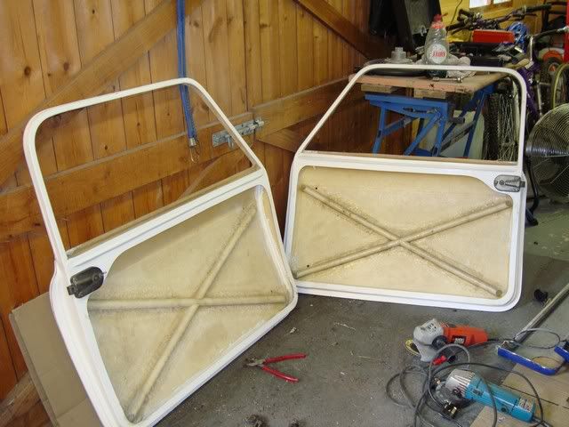
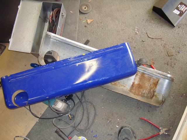
If you have read the beginning of the thread you might remember that i bought the van as a unfinished project it came with both fibreglass and the original steel doors, the fibreglass doors do seem to fit quite well, but i don't have a clue about how to open up the frame to accept the window seal / runner nor any idea how to bond in something to support the bottom of the windows, so i decided to have a look at the steel doors, the drivers door seems to be in reasonable condition and a check with the spring balance suggests that there would not be a massive weight saving using the fibreglass doors especially after the removal of the steel door pocket, anyway the drivers door fits very will the passenger not so good but has a rotted out section and flexes about quite badly, i have read good things about the mini door company i will have a chat to them about repair and re-skin in alloy
That's it for now, and indeed brings things pretty much up to date
so my fix was a trip to Silicon hoses (luckily only half an hour away) to purchase four 45 degree bends and some alloy joiners.After a lot of careful measuring and cutting i am very pleased with the result
wont be quite so tidy when its got hose clips onI mounted the servo so i could get the brake pipes sorted out, also the clutch reservoir on a alloy bracket, i have chosen to use copper nickel from front to rear, probably not my best decision as i don't really find it too easy to work with and has caused a few headaches
Because of the decision to use copper nickel pipes i found it was going to be very difficult to get them in the tunnel particularly where they have to exit around the frame at the rear, so i have decided to run them along the underside of the floor, not what i really wanted but if secured with some nice clamps i am sure they will be fine.
I have designed the pipe clamps and had my toolmaker (thanks Bri) make up one to see how its going to work, seems ok just need a gap in the paid w
ork so we can make stuff for the van All well and good but i am worried that i may have a clash of mounting points with my seat mounting so i have now ordered seats which will be fixed in place the i can see where i can fix the pipes.
The rigid pipes terminate at the rear on this alloy bracket with braided hose to each rear brake and the clutch, the fuel pipes which will also be copper nickel front to rear will also terminate to flexible at this bracket, i will post more pictures as this idea develops.
If you have read the beginning of the thread you might remember that i bought the van as a unfinished project it came with both fibreglass and the original steel doors, the fibreglass doors do seem to fit quite well, but i don't have a clue about how to open up the frame to accept the window seal / runner nor any idea how to bond in something to support the bottom of the windows, so i decided to have a look at the steel doors, the drivers door seems to be in reasonable condition and a check with the spring balance suggests that there would not be a massive weight saving using the fibreglass doors especially after the removal of the steel door pocket, anyway the drivers door fits very will the passenger not so good but has a rotted out section and flexes about quite badly, i have read good things about the mini door company i will have a chat to them about repair and re-skin in alloy
That's it for now, and indeed brings things pretty much up to date
#66
Alan Carruthers
-

- Members
-
- 226 posts
Mini Mad
Posted 17 December 2011 - 06:17 PM
Mate, absolutely epic work, to echo others comments just love the cnc'd parts.
Would you consider making parts for others?
Al
Would you consider making parts for others?
Al
#67
less is more
-

- Members
-
- 172 posts
Mini Mad
- Local Club: NONE
Posted 17 December 2011 - 08:10 PM
I mounted the radiator to see what needed to be done to connect the coolant pipes, i couldn't figure how the stuff i got from Z-Cars was supposed to work
After a lot of careful measuring and cutting i am very pleased with the result
These may help, they get tighter with heat, think there called gates, saw them the other year on a mini at Bingley

Great project, fantastic engineering work displayed
Andy
#68
rustandoil
-
- Members
-
- 317 posts
Speeding Along Now
- Location: Gloucestershire
Posted 18 December 2011 - 08:38 AM
Thanks for the comments guys as i have said before the encouragement is a real moral booster
Al, no promises as we as still new to the CNC game but PM me a drawing or sketch and we will have a look
Andy, as an engineer i like "mechanical fixings" but those Gates hose clamps would really neaten things up, i will try to beg some samples and see what they are like
link to the Gates hose clip catalogue page
Martin
as i have said before the encouragement is a real moral booster Al, no promises as we as still new to the CNC game but PM me a drawing or sketch and we will have a look
Andy, as an engineer i like "mechanical fixings" but those Gates hose clamps would really neaten things up, i will try to beg some samples and see what they are like
link to the Gates hose clip catalogue page
Martin
#69
stevede
-

- Members
-
- 1,164 posts
As seen on TV
- Local Club: None
Posted 18 December 2011 - 09:03 AM
Just happened across this build thread and am hooked
Loving the attention to detail and the fabrication facilities to get the job done right
Looking forward to more updates
Regards
Steve
Loving the attention to detail and the fabrication facilities to get the job done right
Looking forward to more updates
Regards
Steve
#70
rustandoil
-
- Members
-
- 317 posts
Speeding Along Now
- Location: Gloucestershire
Posted 20 December 2011 - 08:16 AM
It seems one of the problems of building cars like this is the need to have all the parts available to avoid clash of parts or fixings, this could need reworking, something that i wish to avoid.
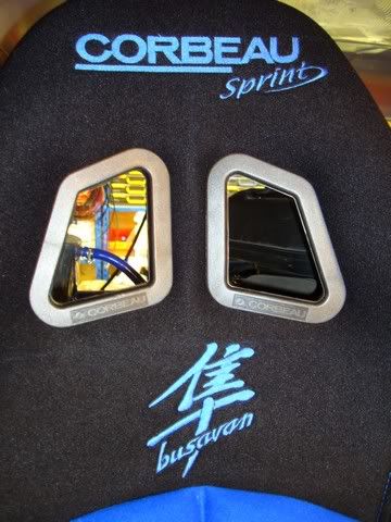
Clearly I don't need seats for ages yet, but in order to ensure the mounting points would not clash with brake, clutch and fuel pipes and their fixings i ordered these Corbeau Sprints with a bit of custom embroidery
Ordered on a Friday afternoon and delivered the following Thursday
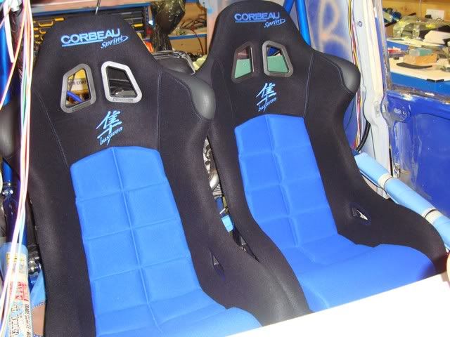
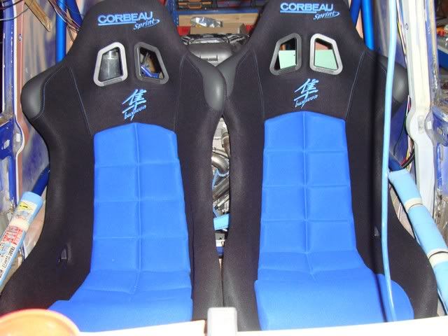
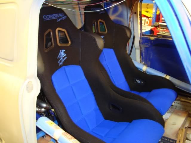
I was told by the very helpful Kathryn at Corbeau that the sprint would fit in a classic Mini but "would be tight" she was not kidding what i failed to realise was that side mount seats are not a "bolt In" job in a Mini, in one of the photos you can see my temporary Dexion subframes to find out how best to squeeze the seats in
We have started to make a new inner side mount for the seats from aluminium section we have also cut and machined some aluminium angle and "T" section for the basis of the seat subframes, very much a "make it up as you go along" job......
There will of course be photos of these parts when we are a fit further on........
Clearly I don't need seats for ages yet, but in order to ensure the mounting points would not clash with brake, clutch and fuel pipes and their fixings i ordered these Corbeau Sprints with a bit of custom embroidery
Ordered on a Friday afternoon and delivered the following Thursday
I was told by the very helpful Kathryn at Corbeau that the sprint would fit in a classic Mini but "would be tight" she was not kidding
what i failed to realise was that side mount seats are not a "bolt In" job in a Mini, in one of the photos you can see my temporary Dexion subframes to find out how best to squeeze the seats inWe have started to make a new inner side mount for the seats from aluminium section we have also cut and machined some aluminium angle and "T" section for the basis of the seat subframes, very much a "make it up as you go along" job......
There will of course be photos of these parts when we are a fit further on........
#71
jagman.2003
-

- Members
-
- 1,307 posts
One Carb Or Two?
- Location: In the shed.
- Local Club: Owner of my own club of Minis
Posted 20 December 2011 - 08:28 AM
Excellent work, very nice machined parts. I'm missing access to a machine shop. This might persuade me to invest in some basic machines. Good to see another project in Gloucestershire. Kepp up the good work.
#72
cptkirk
-
- Members
-
- 1,799 posts
Camshaft & Stage Two Head
- Location: West Sussex
- Local Club: B.M.C. + Chiminiclub
Posted 20 December 2011 - 10:20 AM
The seats look sweet with the embroidery, and yes they do look pretty freekin tight in there.....
#73
jonny f
-
- Members
-
- 1,485 posts
One Carb Or Two?
- Location: Surrey
- Local Club: Boxhill Mini Club
Posted 20 December 2011 - 10:13 PM
Love this build.
All the custom made parts are lovely.
All the custom made parts are lovely.
#74
rustandoil
-
- Members
-
- 317 posts
Speeding Along Now
- Location: Gloucestershire
Posted 21 January 2012 - 04:45 PM
I have removed my diff to fit the reverse ring gear and the engine cradle as part of my quest to lower the engine,.
When refitted with the lower mounts the chain adjuster mount would have fouled the frame so i cut them off
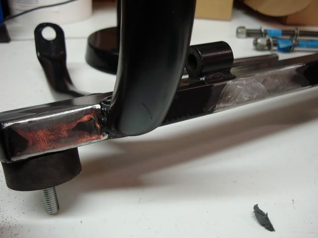
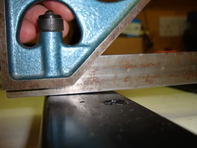
Checking the parts i have discovered more misery the diff mount is all over the place the top mounting holes are not square and don't line up the rectangular section where diff mounts are not square .
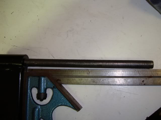
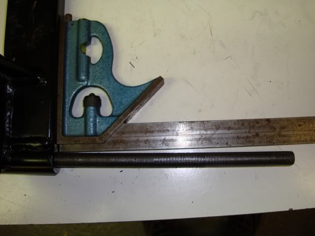
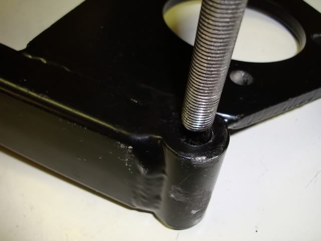
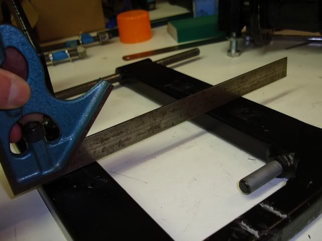
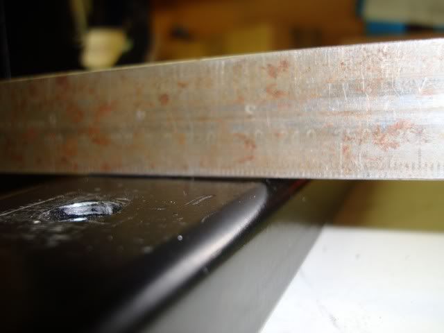
With the diff bolted to the mount it pulls everything around enough that it would (might) work but the top screwed rod needs quite a tap with a mallet to get it through the mounting bushes , with the assembly built up like this the diff rotates with a fair bit of friction, i cant leave it like this so all this is going to be remade, not really a problem but it all takes time.........
Oh and the reverse ring gear supplied is too big
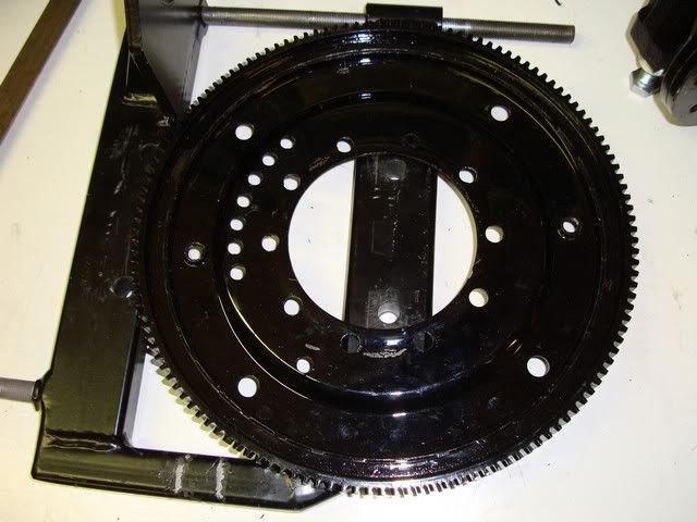
When refitted with the lower mounts the chain adjuster mount would have fouled the frame so i cut them off
Checking the parts i have discovered more misery
the diff mount is all over the place the top mounting holes are not square and don't line up the rectangular section where diff mounts are not square .With the diff bolted to the mount it pulls everything around enough that it would (might) work but the top screwed rod needs quite a tap with a mallet to get it through the mounting bushes
, with the assembly built up like this the diff rotates with a fair bit of friction, i cant leave it like this so all this is going to be remade, not really a problem but it all takes time.........Oh and the reverse ring gear supplied is too big
#75
edsmini
-

- Members
-
- 357 posts
Speeding Along Now
Posted 21 January 2012 - 10:44 PM
all these small problems are sent to try us 
i was looking at the photo of the exhaust manifold and noticed that you have got one of the oil pipes between the exhaust and the engine block. i would highly recommend either re routing the pipe away from that area or getting some heavy duty heat insulation wrap to cover the braided hose. when i had my mini out for a blast at night after returning home you could open the bootlid and clearly see the exhaust manifold glowing orange. ( and that was with DEI exhaust wrap) make sure you give plenty of thought when running wires hoses near the exhaust. no one would believe the heat that comes off the manifold after you have been giving the engine death.
leave at least 2" between the aluminium bulkhead and the exhaust to allow air circulation, although your design of frame where the exhaust would have originally been will allow some air to get in and around the exhaust.
leave some space between the bulkhead and your seat otherwise the heat might damage your cracking seats.
Keep the pics coming, all this info helps the fellow builders
Ed
i was looking at the photo of the exhaust manifold and noticed that you have got one of the oil pipes between the exhaust and the engine block. i would highly recommend either re routing the pipe away from that area or getting some heavy duty heat insulation wrap to cover the braided hose. when i had my mini out for a blast at night after returning home you could open the bootlid and clearly see the exhaust manifold glowing orange.
( and that was with DEI exhaust wrap) make sure you give plenty of thought when running wires hoses near the exhaust. no one would believe the heat that comes off the manifold after you have been giving the engine death.leave at least 2" between the aluminium bulkhead and the exhaust to allow air circulation, although your design of frame where the exhaust would have originally been will allow some air to get in and around the exhaust.
leave some space between the bulkhead and your seat otherwise the heat might damage your cracking seats.
Keep the pics coming, all this info helps the fellow builders
Ed


1 user(s) are reading this topic
0 members, 1 guests, 0 anonymous users


