HAYABUSA POWERED COOPER R.W.D.
#376

Posted 15 May 2006 - 07:07 PM
#377

Posted 15 May 2006 - 10:42 PM
and a good idea is to get both the inlet and the outlet of the cooler renforced with a bit of brazing thrust me i knowd i even caused a brand new oil cooler to leak buy just giving if a small tweek
#378

Posted 15 May 2006 - 11:03 PM
just a little note on the hose you fitted on the oil cooler hydraulic hoses are not ideal for an oil cooler for a couple of reasons 1. there not rated to the temperature your after 2. they are quite rigid and can cause your oil cooler to crack at the neck of the cooler from vibration. most hydraulic hose are only rated to about 95 degrees what u need is stainless 1/2" conveluted ptfe lined hoses which are rated to 130 degrees and are half the weight as well
and a good idea is to get both the inlet and the outlet of the cooler renforced with a bit of brazing thrust me i knowd i even caused a brand new oil cooler to leak buy just giving if a small tweek
Thanks for the tip, The hose hasnt got a steel armour reinforced liner in it as it would be far too heavy for what im building anyway, it has a pressure rating of 130psi and a temp of 140' stamped on it as it was "ideal for what i was using it for" said the man behind the counter!!!
I dry sumped my old rally car in 3/4" single wire hose and i weighed a ton but was a lot cheaper than Aeroquip / Goodridge!!!
Cheers
#379

Posted 16 May 2006 - 02:26 AM
Where did you get your HID kit?
Thanks,
Monte
Bloody hell, best not go out in the rain when its dark then!!!
The heated front screen draws 30 -40 on its own!!
Good job i got Hid front lights which only draw 35 w each
Cheers
#381

Posted 20 May 2006 - 07:21 PM
Anyway got a lot done today and finished off a few jobs that i was awaiting bits for etc,
Now starting to see it take shape
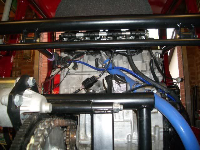
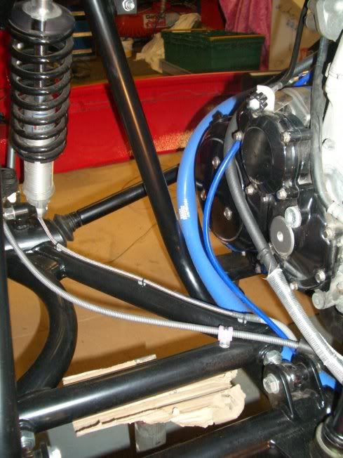
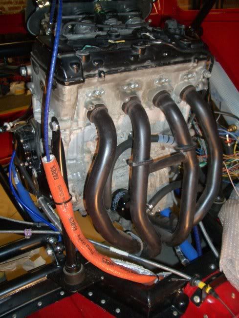
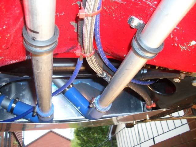
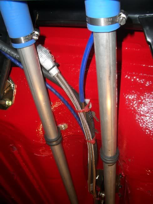
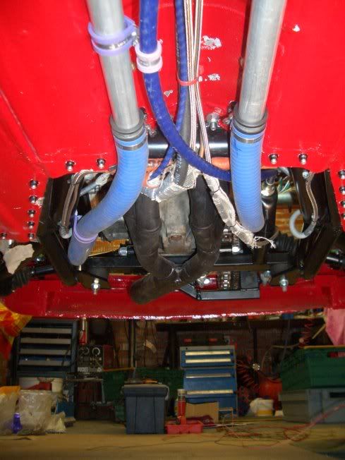
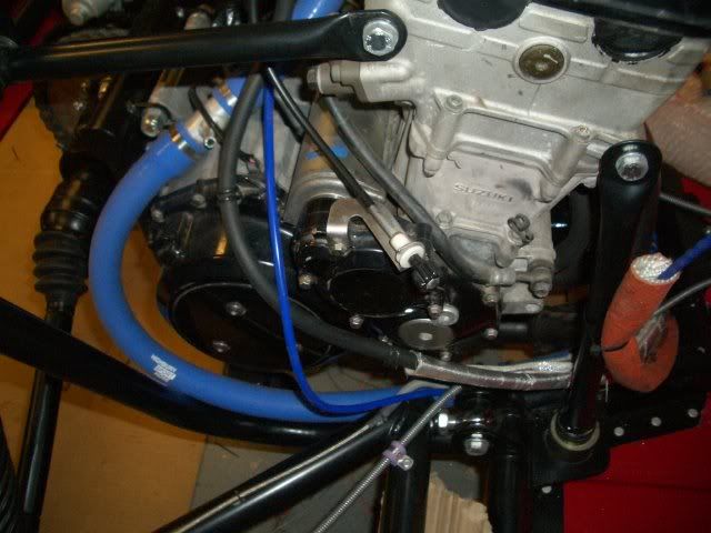
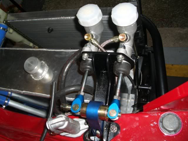
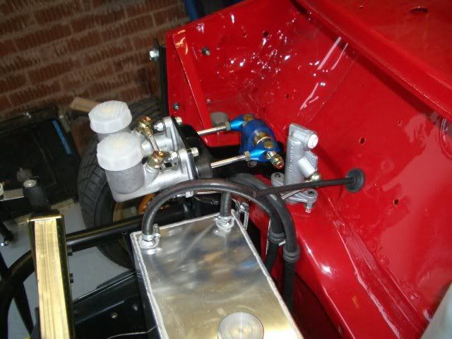
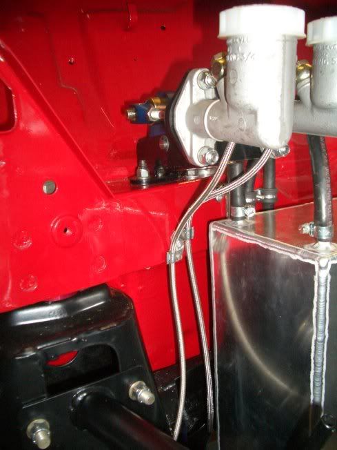
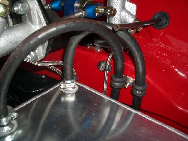
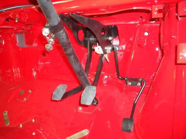
Phew that enough for now!!!
Its nearly ready to fire up now, just a bit of the engine loom to finish off and mount the bike can.
Cheers
#382

Posted 21 May 2006 - 02:13 AM
wayne
#383

Posted 21 May 2006 - 08:37 AM
You'll be able to drive it to the Weston-Rhyn mini club soon then
Can't wait to see it finished Mark, you sure are making good progress with it
#384

Posted 21 May 2006 - 08:48 AM
can i ask whats the idea with the 2 center pipes being joined together on the exhaust manifold ?
#385

Posted 21 May 2006 - 09:23 AM
looking good
only surprising thing is the amount of times the pint has chipped off in the centre tunnel? ive found 2k to be extremely tough?
wayne
It is the stonechip that has come away but only in the tunnel as that is where we supported the shell so when its finished it will be less noticeable, dont forget, it was stonechipped and painted and back in my garage in 3 working days so it had hardly had time to go off!!
As for the tube in the centre of the manifold, it is purely for braceing purposes only???? Suzuki made it like that???
Must be there for a reason.
cheers
#386

Posted 21 May 2006 - 09:30 AM
Kind off worrying when you take away the forced induction and fitt it in the back of a mini......
Full remap the only safe way as Far as I'm conserned....
Ps a friend of mine Mapped a highly modded Busa motor last year, still 1300cc but reved to 14500rpm, did
300bhp without turbos etc......
#387

Posted 21 May 2006 - 09:50 AM
Best ask Suzuki as they are standard Busa Pipes...... But to realy though a curve ball into the equation then what you should ask is why the hell does the standard ECU have different fuel and Ignition maps for cylinders 2-3 over cylinders 1-4 ????? even if the standard induction box has different lenght trumpets ?????...
Kind off worrying when you take away the forced induction and fitt it in the back of a mini......
Full remap the only safe way as Far as I'm conserned....
Ps a friend of mine Mapped a highly modded Busa motor last year, still 1300cc but reved to 14500rpm, did
300bhp without turbos etc......
Dynojet power commander on the shopping list and a set up at TTS rolling road once it is finished before any serious use but it will be ok to get it up the road and MOT etc for now.
It has diferent length trumpets as the ram air system enters the the airbox at the sided in the front bottom area and then a vacum controlled flap opens when the speed reaches a certain point so the forced air would go straight in the centre 2 trumpets so they make em longer to give the outer cylinders a chance as it would have a certain amount of positive air pressure in their at high speed.
Now it is on a foam filter they all got the same amount to draw on, but you already knew that didnt you (F1MINI!)
cheers
#388

Posted 21 May 2006 - 10:03 AM
Could you tell me the gap between sprockets in your picture
Cheers
David
Attached Files
#389

Posted 21 May 2006 - 10:23 AM
Hello Mark,
Could you tell me the gap between sprockets in your picture
Cheers
David
Hi, the centres are approximately 8 1/4" between them. Give or take a bit as i couldnt see the engine sprocket clearly as it has the cover over it a bit and i was leaning in and looking down.
Cheers
#390

Posted 21 May 2006 - 11:35 AM
2 user(s) are reading this topic
0 members, 1 guests, 0 anonymous users
-
Bing (1)


