
You will need to drive the car up onto a set of ramps, or jack the front and securely support the vehicle under the floorpan, ensuring you don't cause damage to the floor of the car.
Then disconnect the battery as a precuation, as you will be working in the confines of the engine bay.
Now you can start!
1 - First of all, open the bonnet of your Mini:
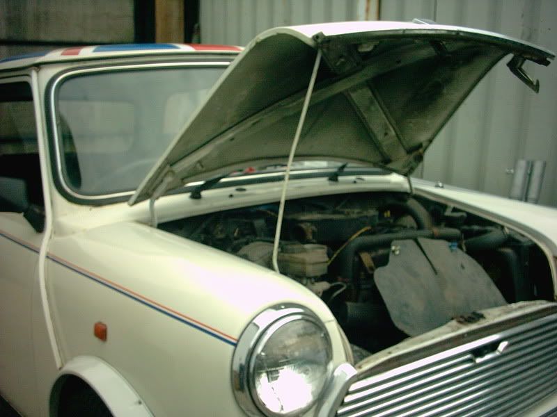
2 - Then remove the ignition splashguard (if fitted), airbox and grille, leaving an exposed engine bay:
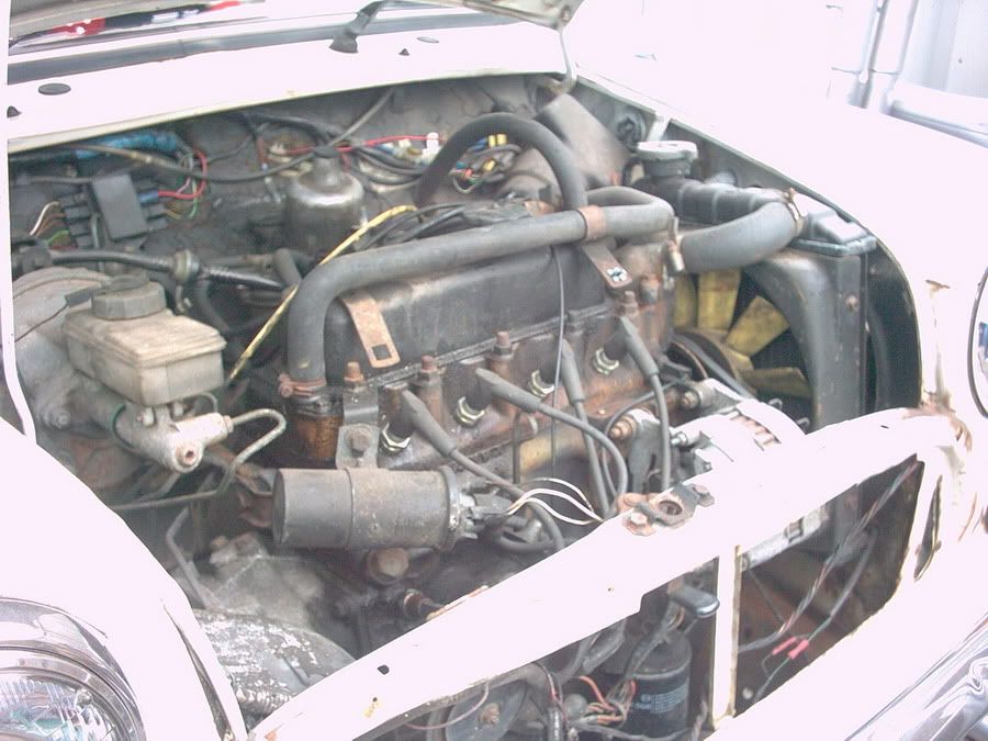
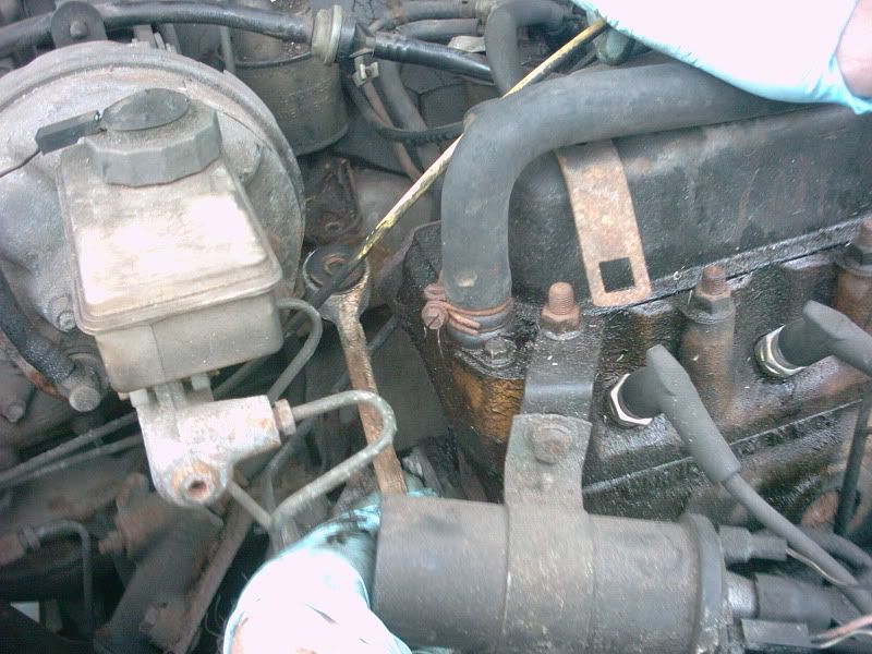
We will start with the engine - bulkhead steady, mounted on the right hand side of the block and the bulkhead beneath the clutch master cylinder:
3 - Undo and remove the bolts securing the front of the engine steady bracket to the block. They're 1/2" AF, and should come undone easily:
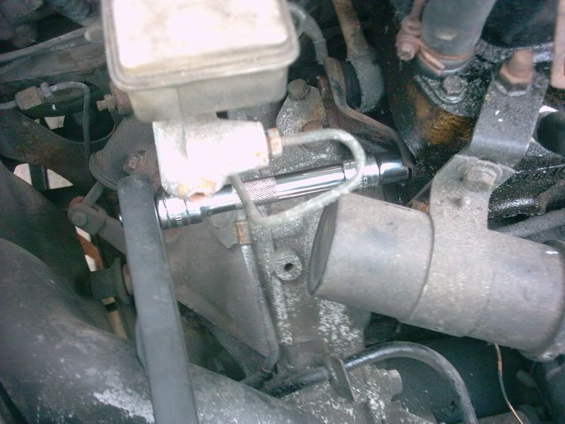
Once undone, remove the bolts, and retain the bracket and washers in the correct order.
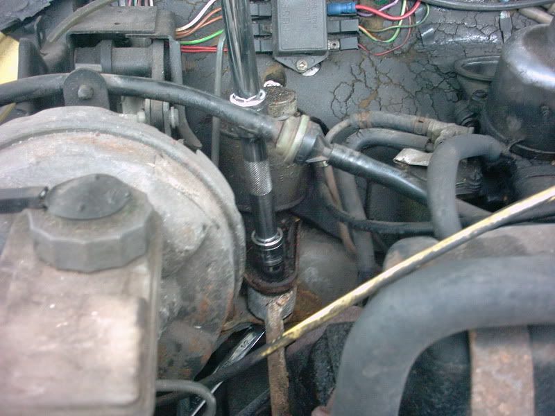
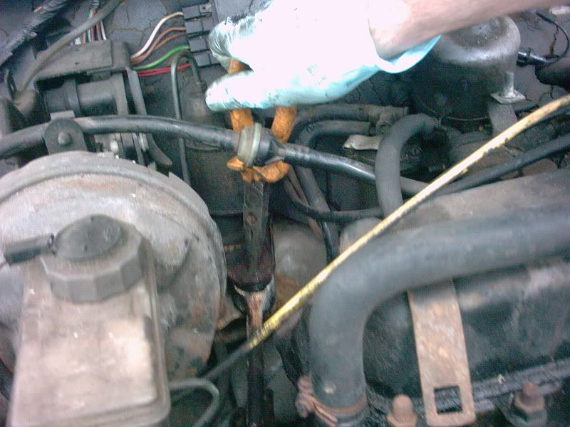
4 - Next, using a 1/2'" AF spanner on the bottom, and a 1/2" socket and long extension, remove the bolt securing the rear of the steady to the bulkhead. Make sure the nut on the bottom doesn't round off, as it is usually a softer brass nut. Attached to the bolt should be the main engine earth strap, make sure this isn't lost. The other end will have been disconnected when you undid the front bolts:
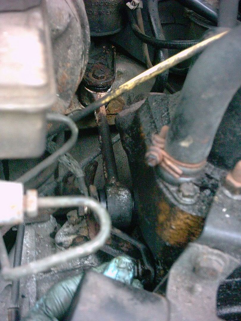
5 - Carefully withdraw the engine steady bar from the engine bay, being wary of damaging brake pipes etc. It can sometimes be tight in the rear bracket, so some force may be needed. Don't trap your fingers or bang your elbow, as it can sometimes come free quickly:
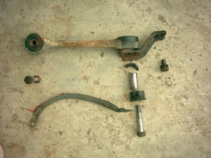
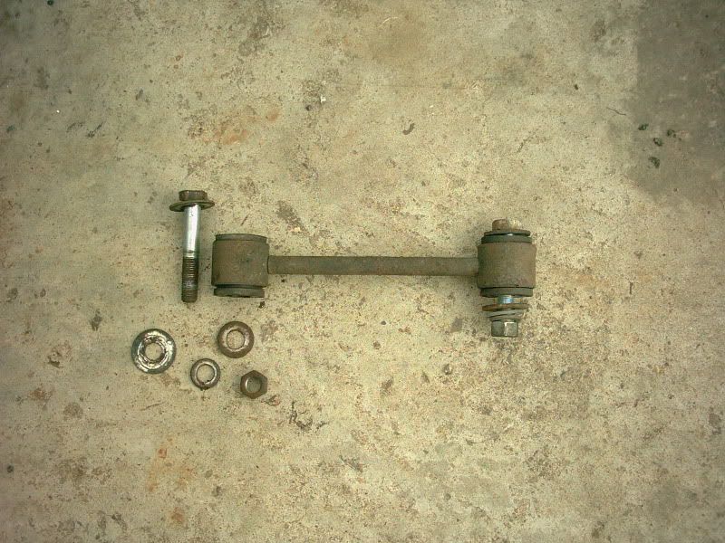
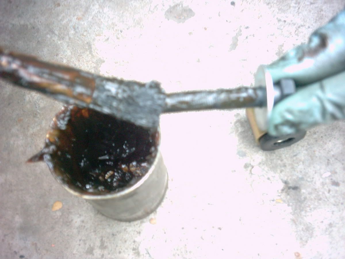
6 - This picture shows the engine steady off the car, and its components. As can be seen, the bushes on the engine side are shot, with one almost completely disappeared. This was causing a large amount of engine movement, which in turn ripped the rear exhaust middle mount from the subframe. If your engine has been moving for a while, be sure to check the rear exhaust system mountings for damage. (the earth strap is shown too, for reference):
7 - Next, remove the front r/h engine steady (if fitted). Most Mini's post 1984 will have this steady. It mounts onto a bracket on the front subframe, and to a bracket close to the oil drain plug.
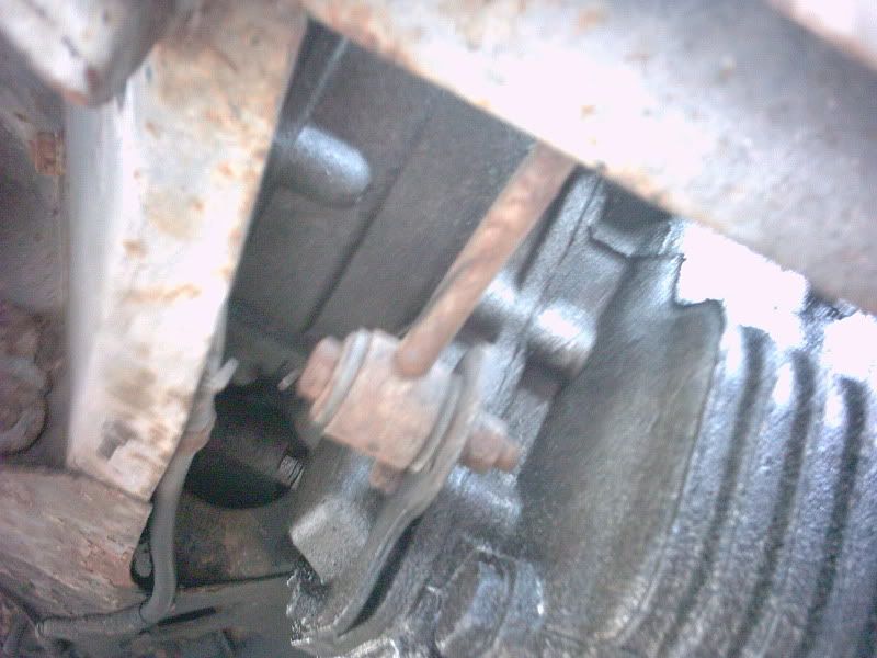
It is secured with 2 bolts, both 9/16" AF. The bolt is often corroded, this one required lubrication and some elbow grease to remove. Once the 2 bolts are undone, the steady will come off. Here it is, as it came off, complete with bolts and bushes:
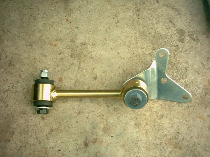
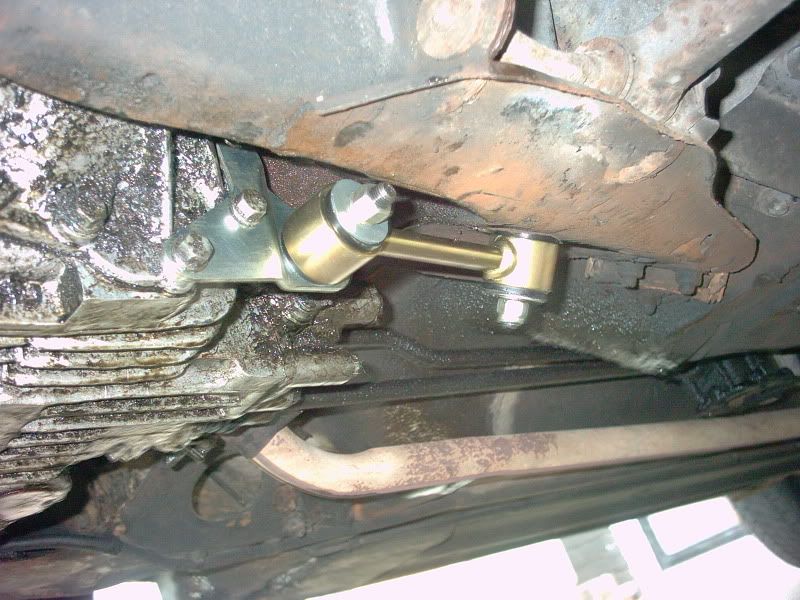
9 - This is the new engine steady. Designed to fit onto the l/h of the gearbox, at the bottom, utilising three of the speedo housing bolts. It then goes back and mounts onto a pre-exisitng hole in the l/h rear leg of the subframe:
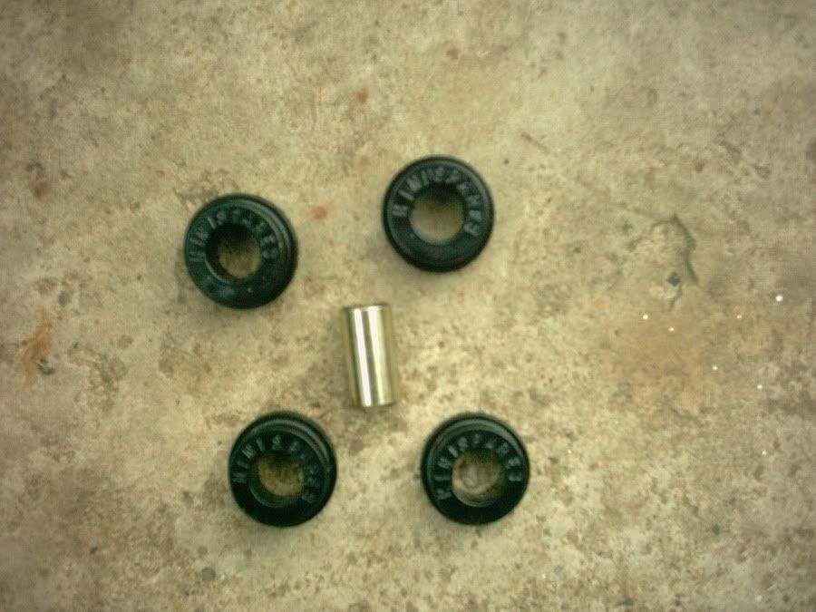
10 - As an upgrade we decided to fit poly bushes to the engine steadies, here is what is included in the engine steady upgrade kit, as purchased from Minispares:
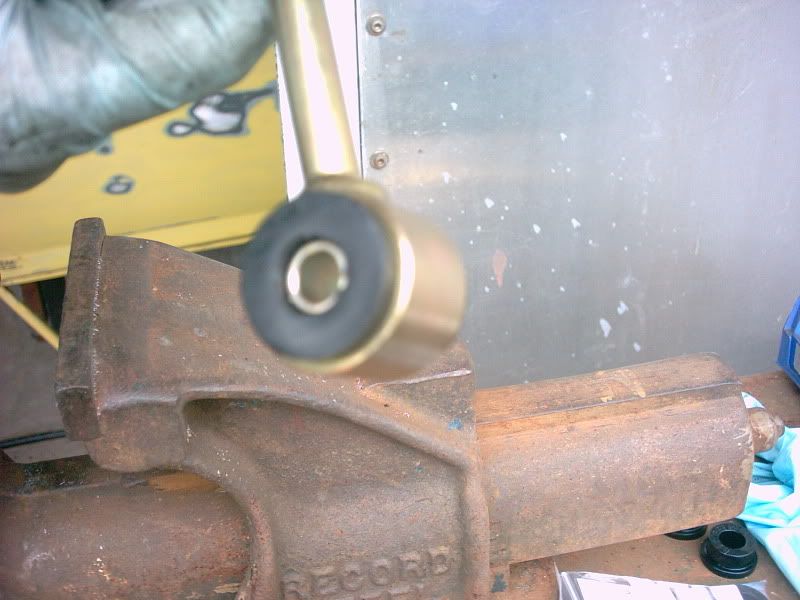
11 - Converting the engine steadies from rubber to poly bushes is easy. First, prise out and remove the rubbber bushes from the steady bars. Then, using a small amount of grease to prevent corrosion, insert the poly bushes, with the flange on the outside, into the steady bar. Then, using a vice (if possible, if not, a hammer and and a piece of wood would be ok), press the steel inserts into the bushes:
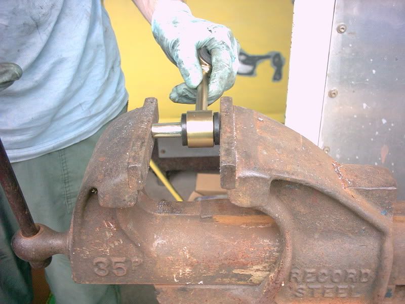
(the bush kit from Minispares only includes 1 new steel insert, you can re-use the existing ones to do the other end of the steady bar)
The finished article should look like this:
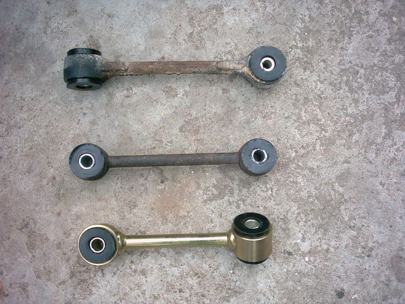
12 - This shows the three different types of steadies. The top one is the upper r/h engine-bulkhead steady, with the ends offset at 90 degrees. The middle one is the lower r/h gearbox-subframe steady, with the ends parallel. The lower one is the new lower l/h gearbox-subframe steady, with the ends offset at 45degress. All have been converted to polybushes, ready to fit:
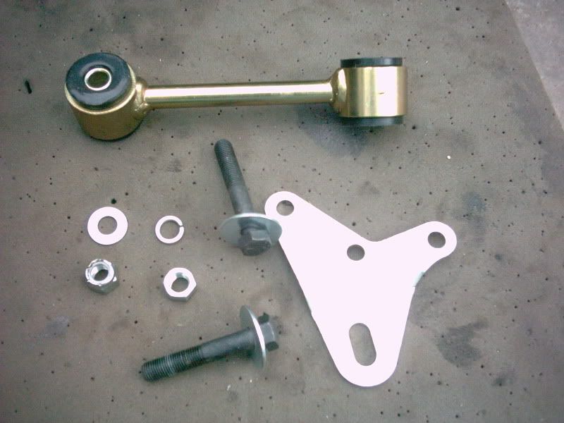
13 - This shows the new engine steady in component form. I added an extra spring and flat washer for security, as the kit only provided them for one bolt. M(8) stainless washers were used:
14 - Next, offer up the bracket for the new steady to the speedo drive housing, and carefully undo the three 7/16" AF bolts needed to fit it. Fit the bracket, ensuring not to overtighten the bolts and risk damaging the aluminium gearbox casing. This shows the bracket fitted:
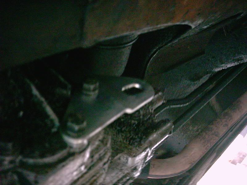
15 - Fit the steady bar to the bracket on the gearbox, and then swing it up and mount it to the hole in the subframe rear leg. There is adjustment for length on the bracket. Leave the bolts slightly loose for the time being. This shows the bracket fitted:
16 - Next, re-fit the upper engine steady to the block and bulkhead. A trick to align the holes on the bulkhead bracket with the steady is to use a pair of long-nosed pliers, and gently lever the holes so they align:
Then, re-fit the bolts, not forgetting the engine earth strap. You can tighten the bolts up fully. This will secure the engine initially, and allow you to make sure the other two steadies are in the correct place:
You can then re-fit the front lower steady, re-fitting, as Haynes says, is the reverse of removal!! Tighten the bolts fully, and also tighten the bolts on the new rear steady (if fitted).
The engine should be held in a vice-like grip by the uprated steadies. Check all nuts and bolts are tight, and re-fit the airbox, ignition guard and grille. Make sure none of the wiring has been disturbed or damaged, then re-connect the battery. Before moving the vehicle, test all lights, horn, wipers etc.
You can now go and drive your beast, and feel how much better it is now the engine doesn't flop about!!
Handy Hint: ALWAYS grease bolts when re-fitting any component!!
This will protect the parts from corrosion, and will also make it so much easier to remove, should you ever need to!
Thanks to minipixie for the loan of her car to do this FAQ, and for being a brilliant photographer! And for sitting patiently all the way through this work!