Jump to content


Photo
- - - - -

Acewell Gages


  • Please log in to reply
20 replies to this topic

#16 dklawson

dklawson

    Moved Into The Garage

  • TMF+ Member
  • PipPipPipPipPipPipPipPipPipPipPip
  • 10,923 posts
  • Name: Doug
  • Location: Durham, NC - USA
  • Local Club: none

Posted 31 December 2008 - 01:27 AM

Pot joint = driveshaft inner CV joint (Mini Spares part GCV1102)
as opposed to the yoke-type driveshaft inner joint on my car.

See this PDF at Somerford.
http://somerford-min...riveFlanges.pdf
My car has yoke-type driveshafts (parts 1 & 2 at the top of the page)
Later Minis have CV joints (pot joints) on their inner ends (item 31 that goes on shafts 28 & 29)

The picture link below shows a Hamlin (industrial brand) reed switch mounted on a bracket bolted to my gearbox. The Sigma magnet is mounted in the end of a QL-5000 u-joint for my yoke-type inboard driveshaft joint.
http://home.mindspri...maBracket01.jpg

EDIT:
Also see this old thread on the topic
http://www.theminifo...showtopic=50424
and for another person's project there are some tiny pictures at...
http://www.six-ex.co...367tproject.htm
(The following tiny picture shows magnets bonded to his car's pot joint)
http://www.six-ex.com/umw367t5.jpg

Edited by dklawson, 31 December 2008 - 01:37 AM.


#17 Marky Tizz

Marky Tizz

    Up Into Fourth

  • Members
  • PipPipPipPipPipPipPipPipPip
  • 2,434 posts
  • Location: Carshalton
  • Local Club: LSMOC

Posted 31 December 2008 - 01:42 AM

Right, OK, I think I have it now. I was getting confused as I had the magnet and reed switch all the way at the back of the car through the back plate, whereas you have yours at the front of the car? Am I wrong? And from what I can make out, you have the magnet on the CV joint and the reed switch on the gearbox? Or am I still being special?

Thanks a lot

Mark

#18 dklawson

dklawson

    Moved Into The Garage

  • TMF+ Member
  • PipPipPipPipPipPipPipPipPipPipPip
  • 10,923 posts
  • Name: Doug
  • Location: Durham, NC - USA
  • Local Club: none

Posted 31 December 2008 - 04:06 AM

It sounds like you understand what I've done.

I read on some web sites that extending the reed switch wires on bicycle computers affected the capacitance of the system and therefore was to be avoided. However, that was for a bicycle computer and I don't know if that would apply to the Acewell. Regardless, some of my acquaintances (with MG Midgets) have mounted their reed switches and magnets like you have on a rear drum and there were no issues. You should be fine if you mount the reed switch at the back. I simply chose the front as it was easier to do on my car and it kept the wire length to a minimum.

#19 Phaeton

Phaeton

    One Carb Or Two?

  • Members
  • PipPipPipPipPipPipPip
  • 1,055 posts

Posted 31 December 2008 - 07:48 AM

So that would attach the mechanical speedo into a digi dash? Or am I misunderstanding? Is there a way to run the digidash of OE speedo cable and still use the original speedo clock too? Or will it only run one at a time? I'm currently using the reed switch that came with the 3150 and it's unreliable at best.


You do have to physically cut the outer cable to slide the unit on, we actually cut the whole cable as we have no analogue speedo, but there is no reason why you could not reattach the rest of the cable to keep the analogue working at the same time.

Is that correct? The description made it sound like you cut the cable and inserted this in the middle. That would give you a digital pulse out to an electronic gauge while retaining the mechanical speedo drive. Did I read that incorrectly?


Yes you did, as explained above

The concern I have is the fact as you say that this is a 3-wire device. Reed switches are often used with very low current instruments and as I mentioned earlier, it may require a dedicated interface circuit to allow the 3-wire sensor to connect to the 2-wire connection used by the Acewell speedometer. You can build such a circuit with a few simple components, but it's a bit of work if you're not comfortable with electronics.


There is 3 wires on the unit, +12v, 0v & +5v if I remember correctly, +12v is a switched supply from anywhere on the car, the 0V & +5V is across the output/input of the Acewell. So in effect it's just the Acewell wiring with an extra 12v supply to the unit.

The problem we found with reed switches no matter where they have been mounted is the inaccuracies, bearing in mind we have to SVA these buggies & the speedo is tested at 30, 50 & 70 MPH & has to be >10% error (have I got that the right way?) With reed switches the speedo seems to read correctly most of the time then will suddenly jump to twice the speed you are actually doing. Various models we have had did this at various speeds no two units were the same, this unit has cured the problems.

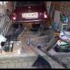
It's still dark at the moment & I'm just off to work, if you want I can take a photo of the unit in place & post it, but it maybe tomorrow depending what time I finish today.

Alan...

Edited by Phaeton, 31 December 2008 - 07:49 AM.


#20 Marky Tizz

Marky Tizz

    Up Into Fourth

  • Members
  • PipPipPipPipPipPipPipPipPip
  • 2,434 posts
  • Location: Carshalton
  • Local Club: LSMOC

Posted 31 December 2008 - 10:21 AM

would be useful to see, kind of tempted by it now when I have a spare £20 lying around...

Doug, thanks for all your help you've been really helpful.
The reed switch did run well on the rear drum for a short period, but I would imagine it's as it got wet/dirty over time it started to get worse, so I may try it on the rear again as I currently have all the rear assy's off, so a bit easier than fiddling at the front of the car.

I'll keep you posted.

Mark

#21 dklawson

dklawson

    Moved Into The Garage

  • TMF+ Member
  • PipPipPipPipPipPipPipPipPipPipPip
  • 10,923 posts
  • Name: Doug
  • Location: Durham, NC - USA
  • Local Club: none

Posted 31 December 2008 - 02:02 PM

With reed switches the speedo seems to read correctly most of the time then will suddenly jump to twice the speed you are actually doing.


That sounds VERY familiar. When I first mounted the reed switch pickup on my car it worked great. On occasion I'd hit about 50 MPH and all of a sudden the digital speedo would jump up and show a speed of 75 or 80 MPH. It wouldn't stop this until you came to almost a complete stop. I attributed it to hitting a resonate frequency of the little finger contacts inside the switch itself but I have no proof that was the cause. I switched to an industrial reed switch mounted on a stiffer bracket and the problem has not returned.

Based on your experience it sounds like the Acewell can directly accept the output signal from the 3-wire sender. That's great information and I hope I can remember this thread when the next Acewell thread surfaces. A cable driven sending unit would be a lot cleaner. Again, the bicycle speedos generally won't work when connected to a 3-wire device.

Mark, let us know your progress and how things work out.


1 user(s) are reading this topic

0 members, 1 guests, 0 anonymous users