Hi Folks,
I have been experimenting with a variable speed control for the Mini heater motor and was wondering if anyone else has done this before? I want to have at least 4 speeds.
I am currently using a Pulse Width Modulator (Home made). Problem is the motor squeals, especially at low speeds, to address this I have had to increase the frequency of the PWM to about 15 MHz, at this frequency the MOSFET that drives the motor is getting very very hot, have burnt finger to prove!
Has anyone else done anything like this? Or does anyone have the specification for the Valeo motor as with this info I can calculate the control parameters better, rather than guessing...
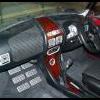
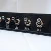
FYI I am also running the heater vent control and heater tap using servos from a model plane, when finished I will have 3 small rotary knobs to control everything, which (should) look awsome!
Cheers
Trog...

Variable Speed Heater Motor
Started by
Trog
, Dec 11 2008 01:08 AM
14 replies to this topic
#2

dklawson
-

- TMF+ Member
-

- 10,923 posts
Moved Into The Garage
- Name: Doug
- Location: Durham, NC - USA
- Local Club: none
Posted 11 December 2008 - 01:20 AM
I have not done this, however, you would probably find it easier to buy a surplus DC motor controller (probably an SCR type) and connect the car's blower supply to the circuit board AFTER the transformer and bridge circuit that will likely be on board. Regardless of whether you're handling this with PWM or a simple variable power supply, certain components are going to get hot.
You said you wanted four speed settings as opposed to fully adjustable/infinite speeds. The way this was handled for years by most manufacturers was very crude yet effective. They hooked up a bank of power resistors in series and placed this bank of resistors along the hot supply line to the motor. Voltage taps were placed at the nodes between each resistor. These taps were then connected to a multi-pole selector switch. Thus, each turn of the selector switch would supply voltage to a node closer and closer to the motor, reducing the series resistance in steps. The first switch setting would pass power through 3 resistors, the second switch setting passed power through two resistors, the next... one resistor. The fourth switch position bypassed all the resistors to supply full power to the blower motor. Obviously the resistors had to be high wattage and they made a lot of heat. They typically are mounted in the incoming air stream to the blower motor so the flowing air cools them.
You said you wanted four speed settings as opposed to fully adjustable/infinite speeds. The way this was handled for years by most manufacturers was very crude yet effective. They hooked up a bank of power resistors in series and placed this bank of resistors along the hot supply line to the motor. Voltage taps were placed at the nodes between each resistor. These taps were then connected to a multi-pole selector switch. Thus, each turn of the selector switch would supply voltage to a node closer and closer to the motor, reducing the series resistance in steps. The first switch setting would pass power through 3 resistors, the second switch setting passed power through two resistors, the next... one resistor. The fourth switch position bypassed all the resistors to supply full power to the blower motor. Obviously the resistors had to be high wattage and they made a lot of heat. They typically are mounted in the incoming air stream to the blower motor so the flowing air cools them.
#3
taffy1967
-

- Members
-
- 9,896 posts
Whovian
- Local Club: South Wales Minis
Posted 11 December 2008 - 04:44 PM
Or fit a post 1996 MPi Mini heater as that had 2 speeds as standard.
#4
dklawson
-
- TMF+ Member
-
- 10,923 posts
Moved Into The Garage
- Name: Doug
- Location: Durham, NC - USA
- Local Club: none
Posted 11 December 2008 - 05:37 PM
The link below is to the closest schematic I could find online that shows the use of a resistor bank to control DC fan speed.
http://www.autoshop1...age/blower4.gif
There is a problem with this schematic. Note the "blue" trace goes directly from the power input (node 5 at the bottom of image) to the end of the resistor (node 1 on the resistor). This connection completely bypasses the on/off/selector switch and would leave the fan running all the time in low speed. Instead, imagine the blue trace going from resistor terminal #1 to the "LO" speed switch position. THAT would be correct for most automotive installations.
Regardless, each time you move the selector switch to the next position, less resistance is present in the fan circuit. On the "HI" selector switch position, the resistor is completely bypassed providing full battery voltage to the motor.
The resistors I used to repair my old VW fan circuit were Dale power resistors in finned aluminum housings. The array I built looked something like that shown in the next JPG. For the fan circuit, the nodes between the resistors would have wires going back to the selector switch... not just the end wires shown in the JPG. (The picture is not mine... it's also just one I found online).
http://www.right-pro...RH501KOHM_1.jpg
OEM automotive blower resistor arrays look like these:
http://www.thesaabsi...ed_resistor.jpg
http://members.train...leResistor2.jpg
http://img.photobuck...0_2792_1024.jpg or
http://www.specialta...sistor-conn.jpg
While they may look different, they all function as shown in the schematic I posted at the top of this post.
#5
basher
-

- Members
-
- 189 posts
Mini Mad
Posted 11 December 2008 - 05:58 PM
can you not take the heater matrix off another make of car like a more modern one and use that as it will have more setting ect.
#6
WiredbyWilson
-
- Traders
-
- 5,004 posts
WiredByWilson
- Location: Kent
- Local Club: WiredByWilson
Posted 11 December 2008 - 06:38 PM
how about fitting a resistor from another car inline with the feed to the motor - or would there be issues with wires melting etc?
#7
dklawson
-
- TMF+ Member
-
- 10,923 posts
Moved Into The Garage
- Name: Doug
- Location: Durham, NC - USA
- Local Club: none
Posted 11 December 2008 - 08:44 PM
Both Basher's and Wilson's ideas will work if you get all the correct bits from the donor car.
The easiest method would be to get the selector switch and resistor array from another car and wire them in series with the existing Mini heater blower assembly.
The easiest method would be to get the selector switch and resistor array from another car and wire them in series with the existing Mini heater blower assembly.
#8
WiredbyWilson
-
- Traders
-
- 5,004 posts
WiredByWilson
- Location: Kent
- Local Club: WiredByWilson
Posted 12 December 2008 - 09:01 AM
you..... mean..... i...... got..... it..... right........ 
*goes for a lay down*

*goes for a lay down*
#9
2lrminivan
-

- Members
-
- 276 posts
Mini Mad
Posted 12 December 2008 - 11:39 AM
i have fitted a vauxhall motor and wiring into my mini u have to make the fan box a bit bigger but it fits, still very tight.
if i was to do it again i would use a smaller fan/motor from a different car.
if i was to do it again i would use a smaller fan/motor from a different car.
#10
WiredbyWilson
-
- Traders
-
- 5,004 posts
WiredByWilson
- Location: Kent
- Local Club: WiredByWilson
Posted 12 December 2008 - 12:06 PM
don't ford ones fit reasonably ok??
#11
dklawson
-
- TMF+ Member
-
- 10,923 posts
Moved Into The Garage
- Name: Doug
- Location: Durham, NC - USA
- Local Club: none
Posted 12 December 2008 - 01:02 PM
Fitting the fan complete from another car is certainly possible as mentioned above. However, these are just basic DC motors moving air. A much simpler approach would be to install the resistor bank and selector switch from another car... leaving the stock Mini blower in place.
You know, it's a bit disappointing that Trog started this thread but hasn't been back to post since starting it.
You know, it's a bit disappointing that Trog started this thread but hasn't been back to post since starting it.
#12
m1n1
-

- Members
-
- 755 posts
One Carb Or Two?
- Local Club: I'm unsociable
Posted 12 December 2008 - 01:27 PM
Sounds a bit complicated.. resistors etc. Why not just fit a rheostat switch? my land rover has one.
#13
Ethel
-

- TMF Team
-
- 25,919 posts
..is NOT a girl!
- Local Club: none
Posted 12 December 2008 - 02:03 PM
A rheostat is a variable resister so essentially the same idea. Does your rheostat incorporate and on/off switch & any details where you got it from? 
#14
Trog
-
- Just Joined
-
- 91 posts
Stage One Kit Fitted
Posted 14 December 2008 - 09:31 PM
Thanks for all your replies.
Sorry not replied sooner but wanted to have a think about things and experiment too over the weekend...
Lots of good ideas... Some thoughts on them...
Fitting a later heater with 2 speed fan is not an option for me as I am in Australia and they cost a small fortune out here (When you can find them)... Is the motor 2 speed of is there a resistor pack somewhere?
I originally thought about a resistor pack from another vehicle but unless the motor matches the resistor pack you won't get the correct speeds. I never thought about changing the motor too which would be a very neat solution.
With work and family commitments I seldom have the time to spend hours trawling the scrap yards for parts (More's the shame). This was why I wanted to get motor specs so I could calculate correct resistor values, pop into Jaycar on the way home and get them...
There were a number or reasons I went the PWM route:
Is uses less power than a resistor system... When a fan is running half speed on a PWM it uses half the current, plus an insignificant amount to run the PWM, when a resistor system runs at half speed the current draw is nearer three quarters...
The rotary switch and wiring on the dash can be small as the current it handles is very small. (Note here: There are 2 reasons I did not go for infinitly variable; firstly even expensive rheostats get "dirty" very quickly and secondly with the very low rotational resistance of these units it would be very hard to adjust the speed when driving.)
Only problem with a PWM is that you can't get 100% power I am running about 98%...
I think Doug L's point was very valid; whatever I do something will be getting hot, either the MOSFET or the resistors, and the MOSFET will be burning far less current so should be far cooler! Your idea of getting an of the shelf DC motor controller is good if I had seen them before I started making my own I would have got one... However all the ones I could find are still PWM and run under 1MHz which would not address the squeal problem from the motor...
Where I am now:
With a large heat sink added to the MOSFET it is now running a lot cooler, if it needs more cooling I thought I could cut a hole in the heater box and put the heat sink in the air flow which I now see is common with the resistor packs anyway... Running at 15 MHz has cured the squeal. Research on the 'net seems to show that this is what is required for these "larger" motors. I have also gone for a full power over-ride using a double pole NO/NC relay so If my PWM burns up I still have a fan!
I will run this for a while and see what happens If it does burn out then I will be trying the resistor ideas mentioned above, probably with the motor as well (I would have thought something out a Fiesta sized car would work well?) as I have just seen that replacement motors are over 200quid from Minispares...
Thanks for all you good thoughts...
Trog
#15
dklawson
-
- TMF+ Member
-
- 10,923 posts
Moved Into The Garage
- Name: Doug
- Location: Durham, NC - USA
- Local Club: none
Posted 15 December 2008 - 01:25 AM
I'm glad you've had some success with this and that changing the frequency addressed the squeal. However, before you say it's "gone", if you are not young yourself, you may want to ask a young kid with good hearing to listen to the fan. You may have just shifted the squeal to a higher frequency that you can't hear.
You've got a solution that's working for you and that's great. Before moving on I'd like to address a couple of comments made above. First, you certainly can use a rheostat as long as you get one rated to handle the current involved. The slower you run the fan, the more heat the rheostat will make. As mentioned, they will in time get dirty but that's probably OK in a car as you'll be changing the speed anyway.
As far as selecting the fixed resistors I mentioned and getting the "right" speeds, that is certainly a trial-and-error thing. On my old VW, there were three very low value resistors (0.25 Ohm?) and each one when added in series dropped the speed by about 1/4. These resistors were rated for high wattage to handle the heat generated. As Trog mentioned, the resistors (both OEM and my repair) were placed in the incoming air stream to the blower so they would be cooled.
If you ever give up on the PWM solution, look for a used motor controller out of a treadmill or similar. You'll have to connect your power in directly to the board after the bridge circuit. Most of these DC motor controllers use a 5k or 10k potentiometer to adjust the speed.


1 user(s) are reading this topic
0 members, 1 guests, 0 anonymous users


