Temp Gauge Wiring Trouble
#1

Posted 07 November 2008 - 02:51 PM
Year:1982
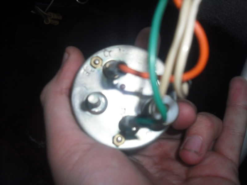
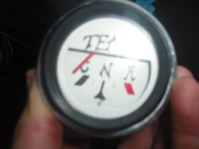
Description of problem: My temp gauge has been wired in but i am assuming its been done incorrectly!
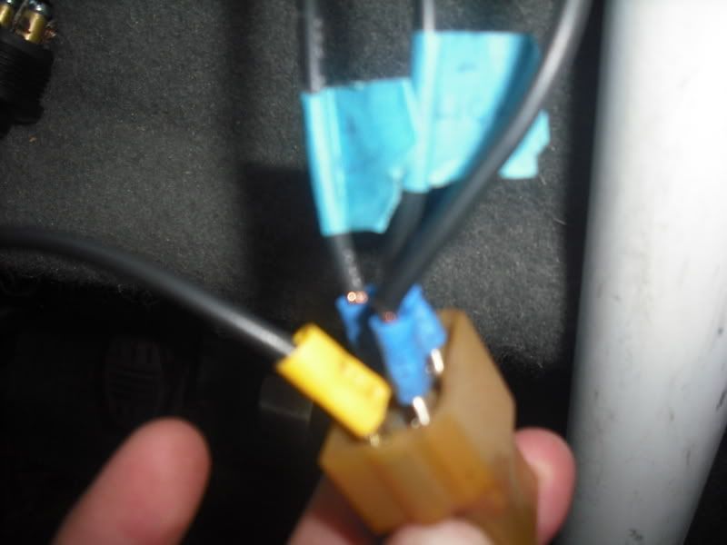
I have 4 wires going into the rear of it 2 are labled Ignition and Light. There is then one that run into the loom and the other one is connected to nothing. what should the other 2 cables be?? i assume one goes to the connection on the engine block! and would the other one be a ground cable??
Any non-standard parts that might be involved with the problem? nope!
im stuck with where the last cable needs to be going!!
#2

Posted 07 November 2008 - 02:58 PM
#3

Posted 07 November 2008 - 03:00 PM
#4

Posted 07 November 2008 - 03:02 PM
im getting a constant cold reading at the moment, so something isnt working somewhere but i cant work it out
#5

Posted 07 November 2008 - 03:09 PM
#6

Posted 07 November 2008 - 03:16 PM
#7

Posted 07 November 2008 - 03:22 PM
A temperature gauge is no different to a volt meter, it's wired between two points and measures the potential difference between the two points. The sender ( the thing in the head ) changes resistance according to temperature. This is a matched pair to the gauge.
One side of the gauge is normally connected to a 10v +ve regulated supply ( in the case of a std mini temp gauge ) or an ignition live feed if the gauge has a built in regulator. The sender is earthed through the block.
Other wires to the gauge are probably illumination or such like.
#8

Posted 07 November 2008 - 03:29 PM
#9

Posted 07 November 2008 - 03:32 PM
the previous owner has labled one with ign (10v +) and another with Light which is obviously for the illumination.
one then goes to the block but its this 4th wire that i cant work out
#10

Posted 07 November 2008 - 03:32 PM
#11

Posted 07 November 2008 - 03:40 PM
so im guessing now that i am missing the ign wiring!!! but really dont know where to wire it to now
#12

Posted 07 November 2008 - 03:48 PM


#13

Posted 07 November 2008 - 03:49 PM
#14

Posted 07 November 2008 - 04:07 PM
The +ve (maybe green) wire needs to be connected to the volt regulator, this is normally the oblong ( 1cm by 3cm ish ) block on the back of the main instruments (speedo), the other line is connected to the sender on the head.
The regulated +10v is already ignition switched live.
#15

Posted 07 November 2008 - 04:13 PM
find it hard to see the back of the speedo though lol so many other wires!!
1 user(s) are reading this topic
0 members, 1 guests, 0 anonymous users


