Jump to content


Photo
- - - - -

Supercharged K20a2 Vtec - Race Spec


  • Please log in to reply
1102 replies to this topic

#1006 cptkirk

cptkirk

    Camshaft & Stage Two Head

  • Members
  • PipPipPipPipPipPipPipPip
  • 1,799 posts
  • Location: West Sussex
  • Local Club: B.M.C. + Chiminiclub

Posted 30 April 2015 - 12:50 PM

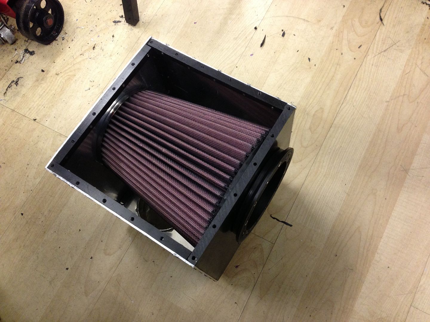
AIR FILTER HOUSING (AFH)


My obsession with feeding cold air to the supercharger has reached new heights. Those of you that have followed this from the beginning will know that I originally had a K&N Apollo, which when I first went to the dyno was told that it was robbing me of about 15-20bhp over an open throttle body (no filter - you can make gains with a well designed intake with filter) and when looking at it now the filter in it is tiny, I mean tiny....


This led me to buy a different filter when I went intercooled, it was much bigger and better but it just lived in the engine bay, near the nearside scoop so wasnt necessarily getting the cold air it should. I guess part of me was thinking "oh well, it's intercooled now so that'll be alright....Nope.....it was pointed out to me at the dyno that the cooler the air going in the cooler the air coming out the charger and therefore the less work the intercooler had to do and therefore a much more efficient setup could have been designed. Also the inlet was all 3" from filter to throttle body.


As with the new throttle body effort this was all brought about by my wanting to re-instate the 72mm throttle body that the car had been dyno'd on, as I know from many many posts on K20 supercharged forums, in the US, that superchargers need as little restriction as possible ahead of the throttle body to make good numbers and there have been gains of over 30hp just from swapping from a std TB (62mm) to a 74mm with 3" piping from filter. Couple that with nice dense cold air and you got a recipe for a good bang.


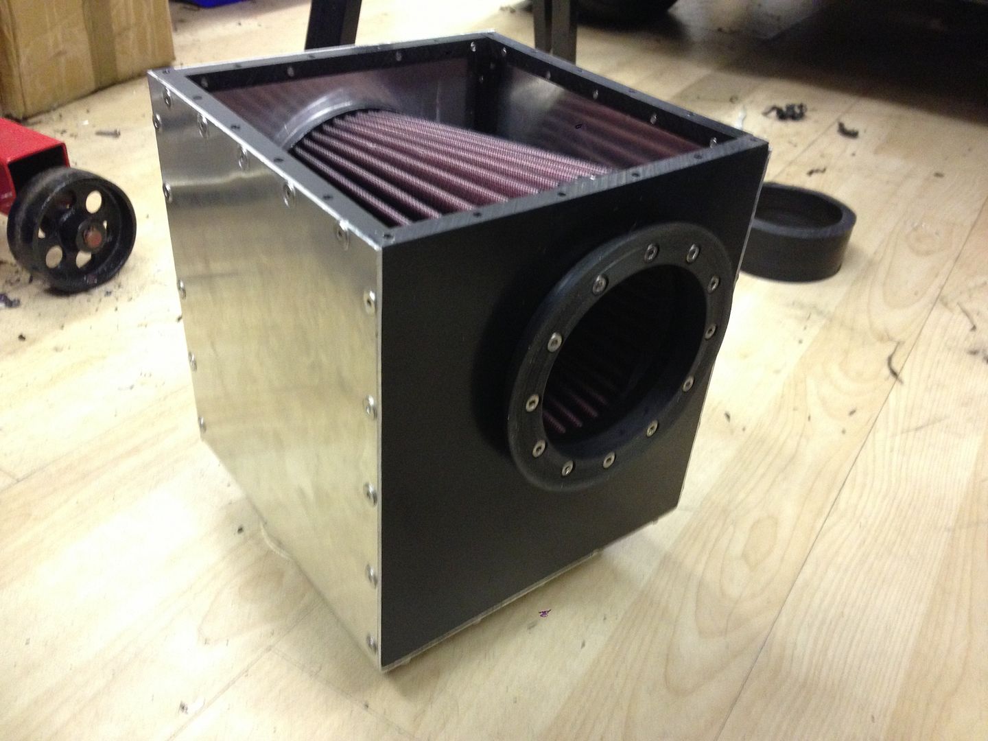
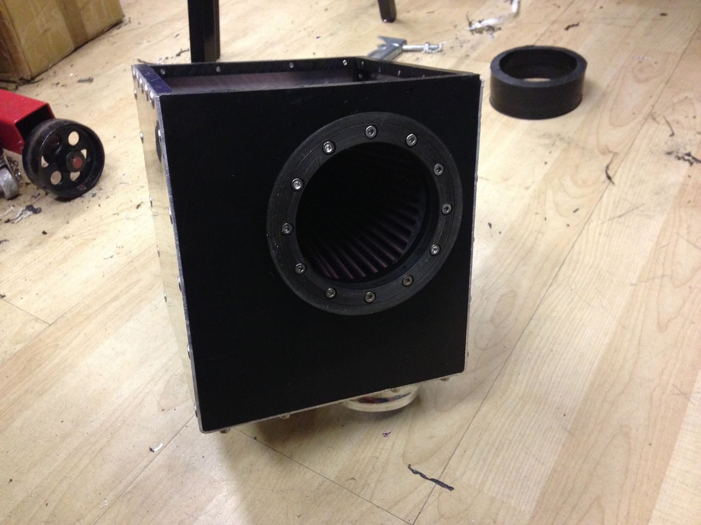
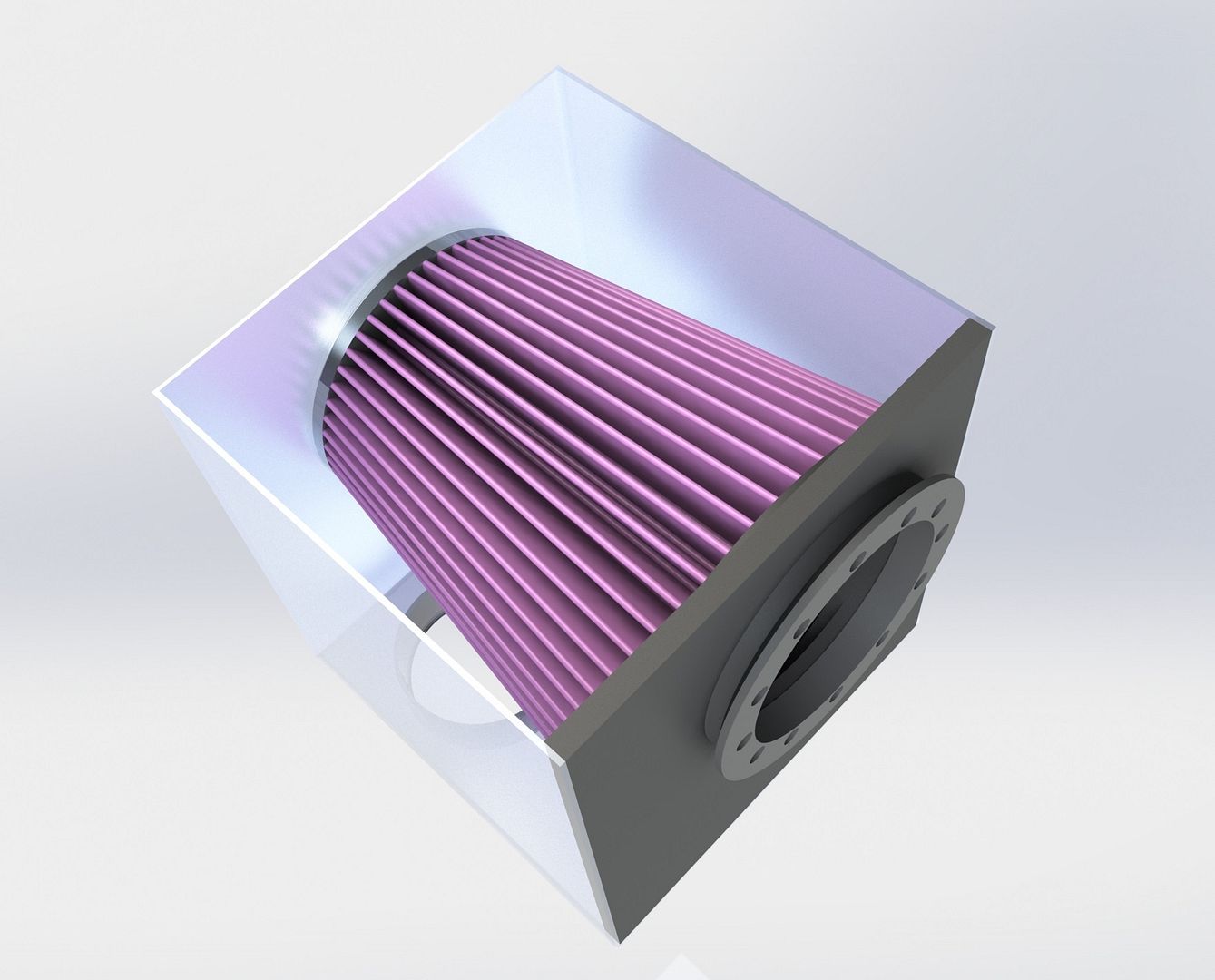
I decided that I needed to suck cold air from both scoops to a bespoke enclosed air filter housing, so that is exactly what I am going to do.....


it will be fed by two 3"/76mm pipes which have a combined cross sectional area greater than a single 4"/102mm, so no restriction there. The air filter is the one you have seen in previous photos of the throttle body setup, with a 4" outlet, actually its not a 4" outlet, its more like 95mm but never mind, its still bigger than the 3" it had before and the area of the filtering fibre is considerably greater than the old one, and p!sses all over the Apollo piece of crap.


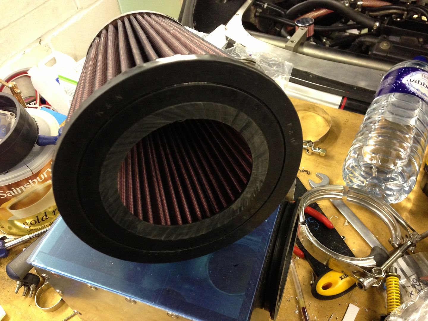
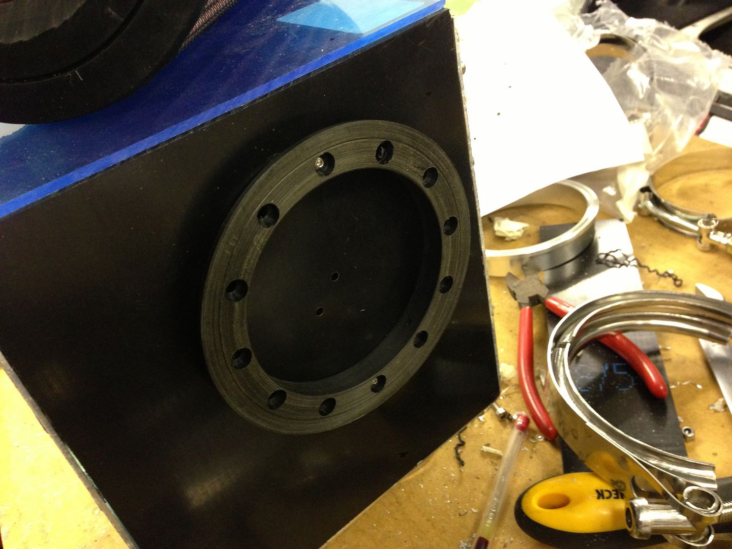
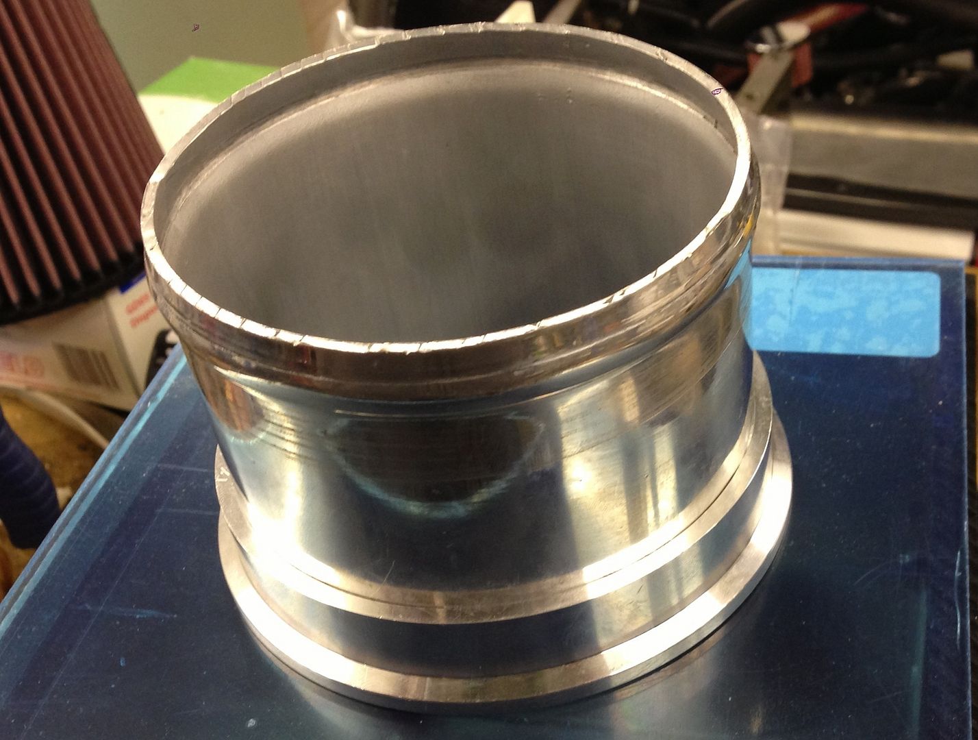
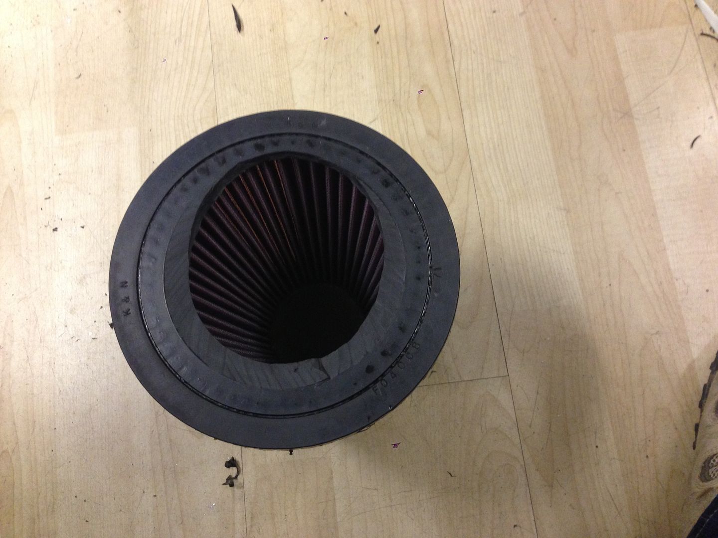
My problem now is that with such a big air filter and housing it cant go where it used to and it is a very tight fit, that tight that with jsut the filter (no housing) i could only jsut get it on the throttle body. So I am utilizing a 4" Vee Band connection so that I can slot the AFH down into it mounted position, this has brought about its own challenges. I have had to make a new half of the vee band from acetal to be able to bolt the connecting half to the AFH, the other half remains aluminium. I have had to cut the neck off the filter to make if fit in the AFH also, that was fun.....not.....


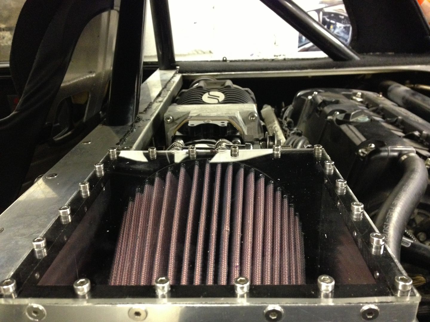
As a nod to the viewing screen I put on the rear parcel shelf I am going to put a clear top to the AFH so you can see the filter as the top of the AFH will sit about 10mm under the perspex of the viewing screen.


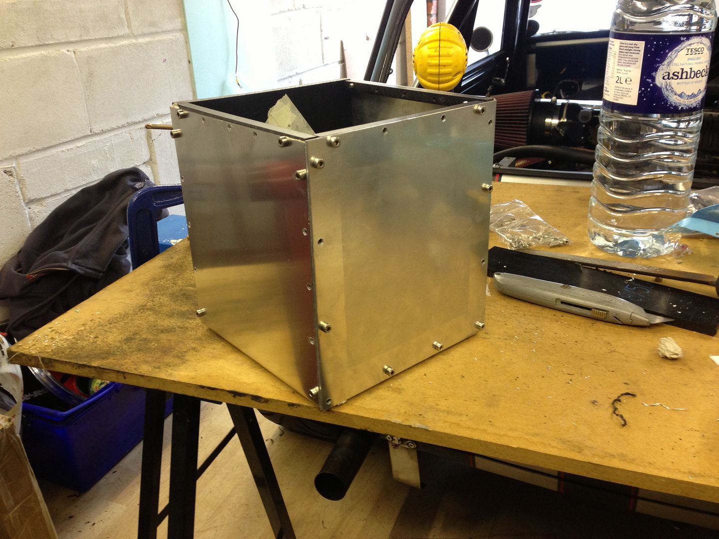
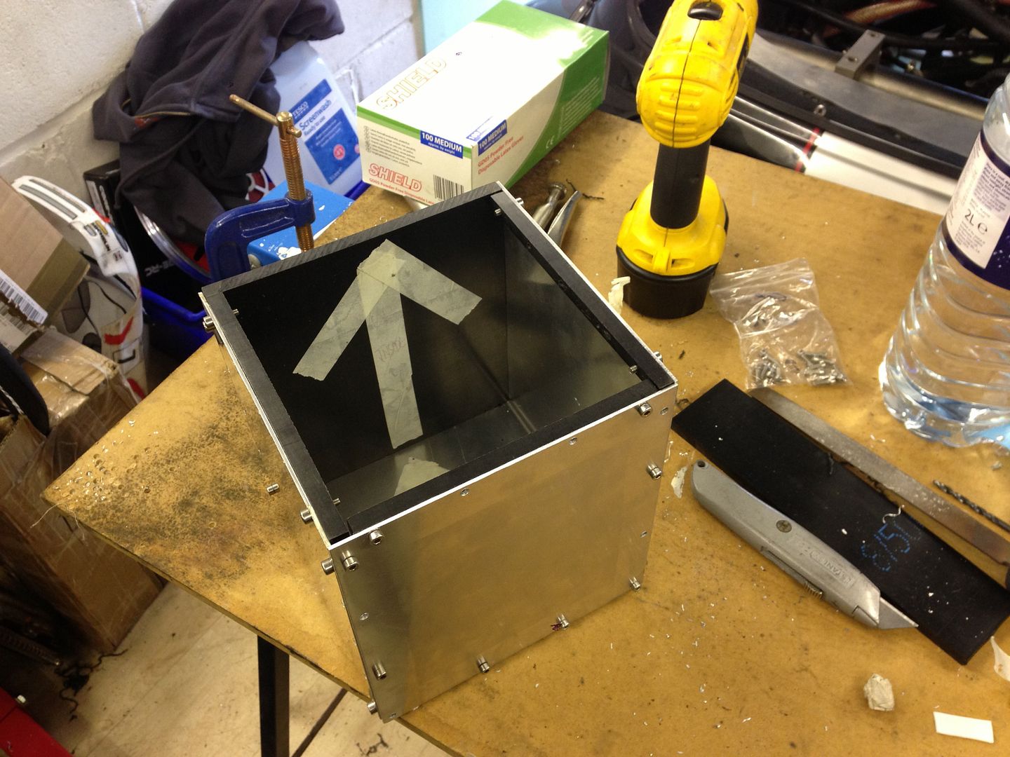
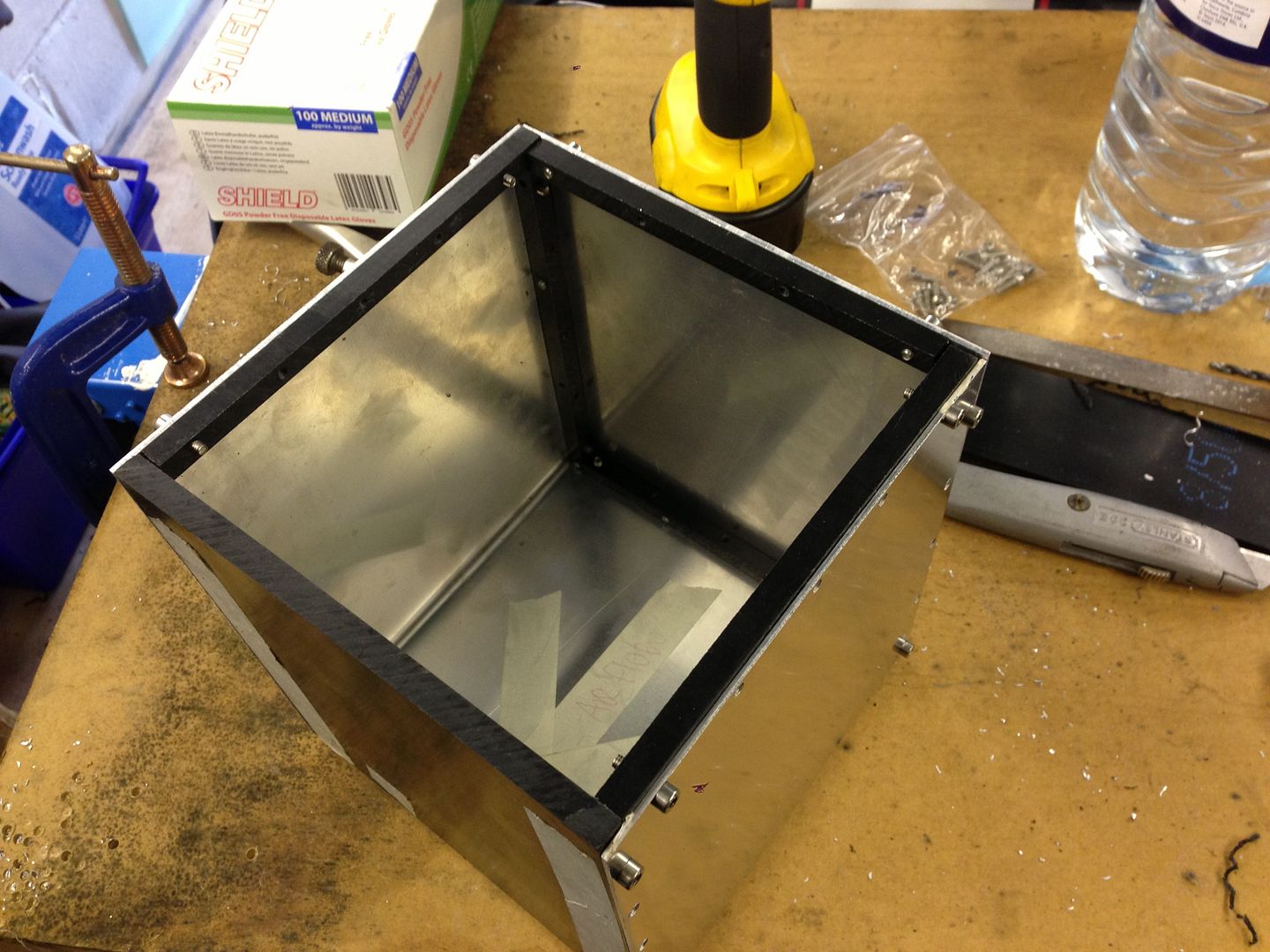
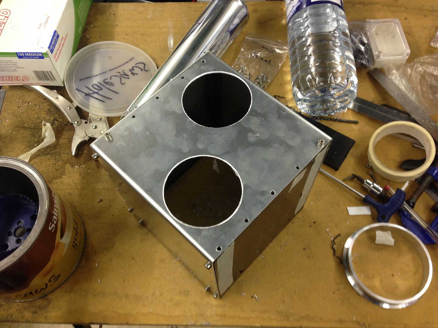
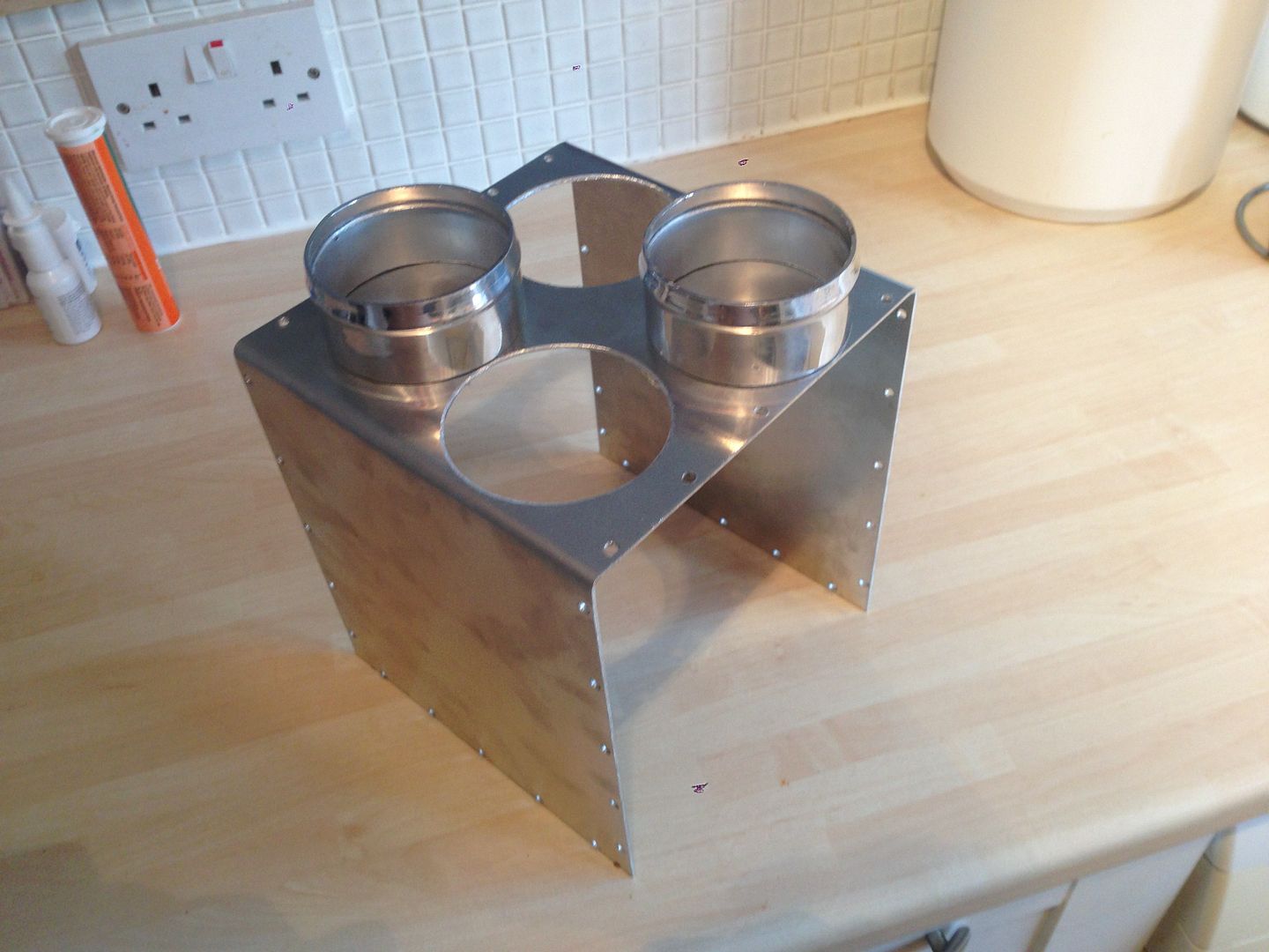
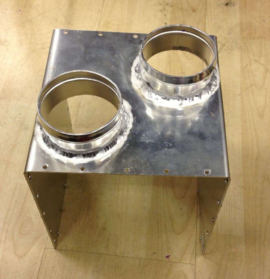
I have made good progress with this but am not quite finished. Here are a few photos of the work undertaken so far:


Basic idea:
 

KampN%20Air%20Filter%20Housing%20for%20J


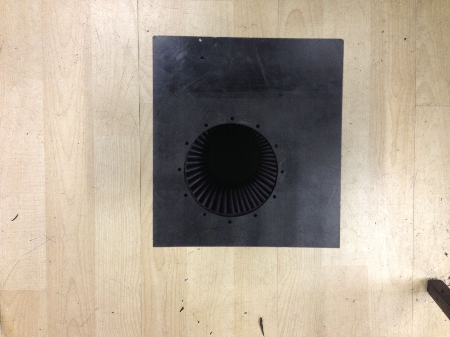
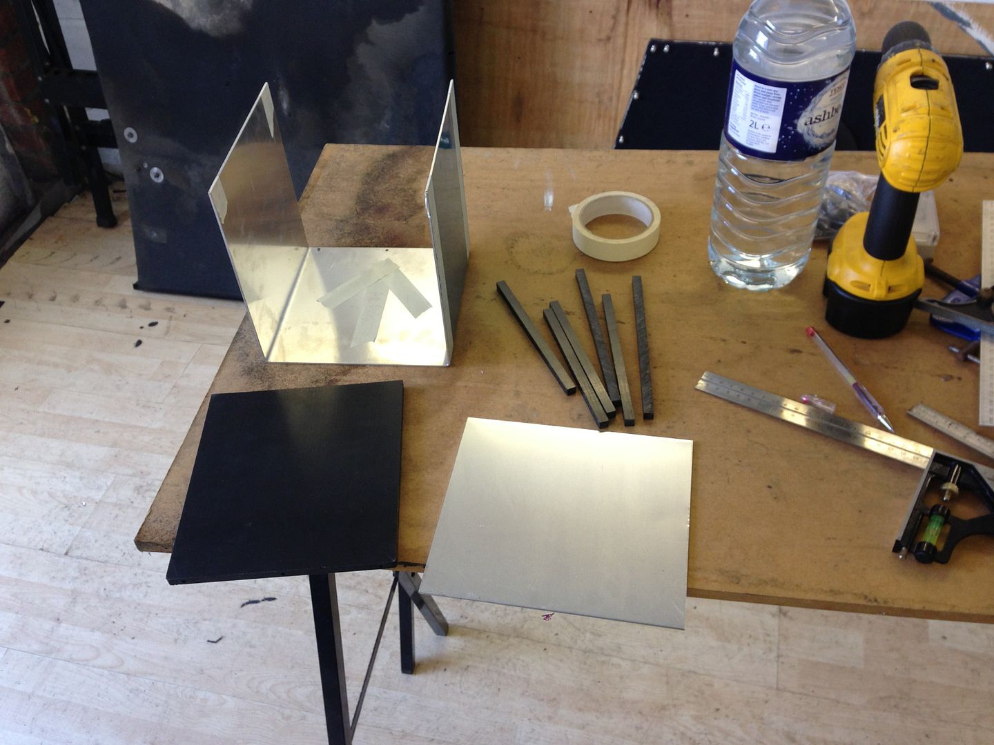
Where I started with the bare material:
 

null_zpspahdshft.jpg


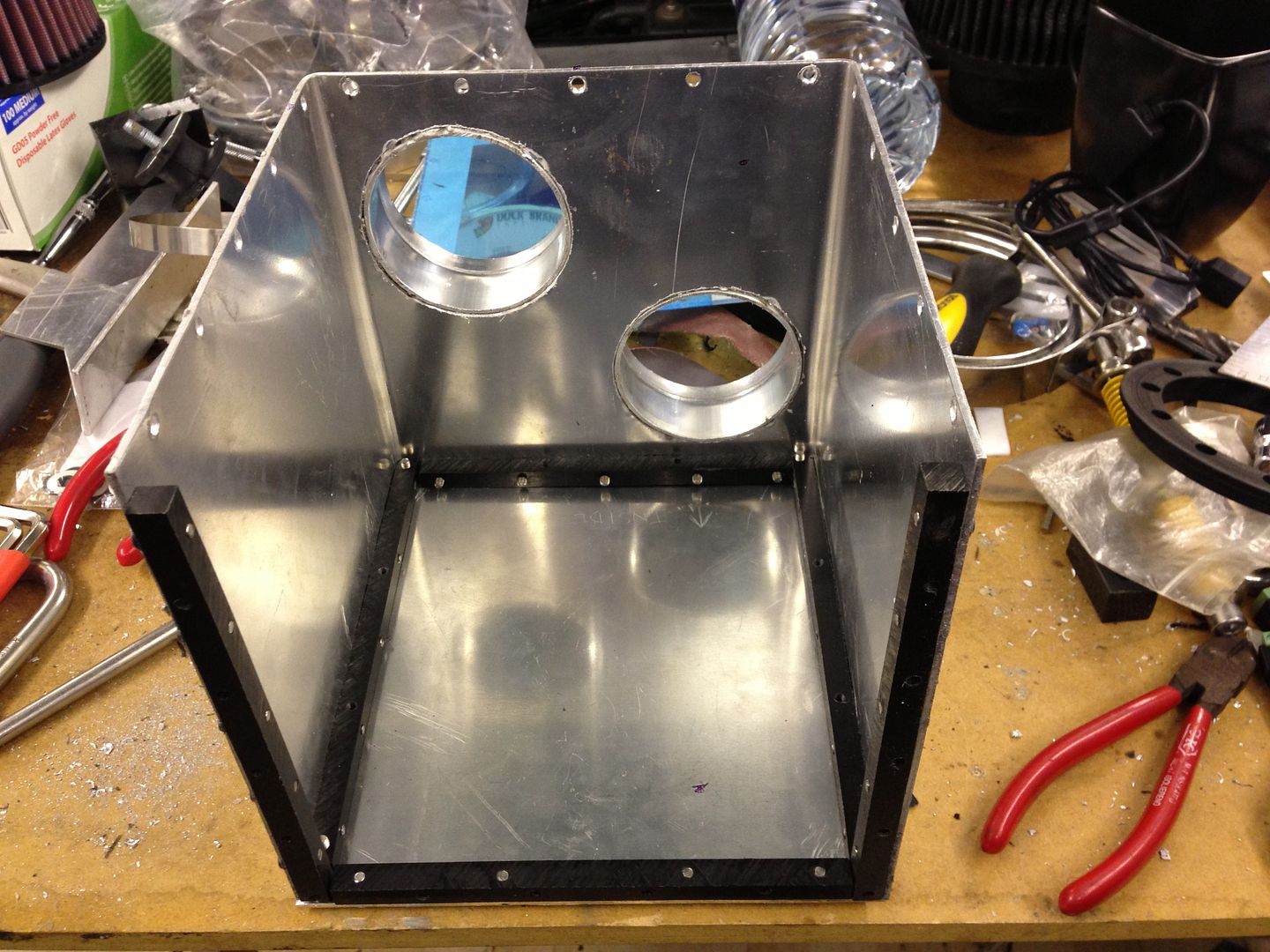
Building it all up:


null_zpscefrmgot.jpg


null_zps8xgnhqbx.jpg


null_zpswst0vxvg.jpg


null_zpsxh2kvz5t.jpg


null_zpsax1jtrtu.jpg


null_zpskppjyhfe.jpg


null_zpszlxsllbf.jpg


null_zpsz76j7ore.jpg


null_zpsuszl3euz.jpg


I will post more as it happens......


.


#1007 MotorinFool

MotorinFool

    Stage One Kit Fitted

  • Noobies
  • PipPipPip
  • 61 posts
  • Location: WA
  • Local Club: Puget Sound Minis

Posted 01 May 2015 - 02:49 AM

I wish I had your welding skills!  Looks good!


#1008 cptkirk

cptkirk

    Camshaft & Stage Two Head

  • Members
  • PipPipPipPipPipPipPipPip
  • 1,799 posts
  • Location: West Sussex
  • Local Club: B.M.C. + Chiminiclub

Posted 01 May 2015 - 08:02 AM

I wish I had your welding skills!  Looks good!


I wish I had my own TIG (only have MIG at home), I have to get this done by a mate, one day I will get myself a TIG and a small Lathe/Mill Combo then I wont have to keep hassling people to do stuff for me. In an ideal world I'd own a laser cutter as well then my life would almost be complete.....oh no, I forgot a 5 axis CNC Mill......then maybe........


Edited by cptkirk, 01 May 2015 - 08:02 AM.


#1009 MotorinFool

MotorinFool

    Stage One Kit Fitted

  • Noobies
  • PipPipPip
  • 61 posts
  • Location: WA
  • Local Club: Puget Sound Minis

Posted 01 May 2015 - 03:43 PM


I wish I had your welding skills!  Looks good!


I wish I had my own TIG (only have MIG at home), I have to get this done by a mate, one day I will get myself a TIG and a small Lathe/Mill Combo then I wont have to keep hassling people to do stuff for me. In an ideal world I'd own a laser cutter as well then my life would almost be complete.....oh no, I forgot a 5 axis CNC Mill......then maybe........


I good TIG system is next on my list of major purchases.  Luckily I have access to a mill and lathe at work I can use after hours, but a CNC mill would be fantastic!


#1010 andream88

andream88

    Mini Mad

  • Members
  • PipPipPipPip
  • 169 posts

Posted 01 May 2015 - 05:36 PM

LOL guys,


I wish I had access to a welder or to a lathe/mill!!!!


#1011 MotorinFool

MotorinFool

    Stage One Kit Fitted

  • Noobies
  • PipPipPip
  • 61 posts
  • Location: WA
  • Local Club: Puget Sound Minis

Posted 01 May 2015 - 08:16 PM

LOL guys,


I wish I had access to a welder or to a lathe/mill!!!!

First world problems...


#1012 cptkirk

cptkirk

    Camshaft & Stage Two Head

  • Members
  • PipPipPipPipPipPipPipPip
  • 1,799 posts
  • Location: West Sussex
  • Local Club: B.M.C. + Chiminiclub

Posted 06 May 2015 - 07:30 AM

AIR FILTER HOUSING (AFH)


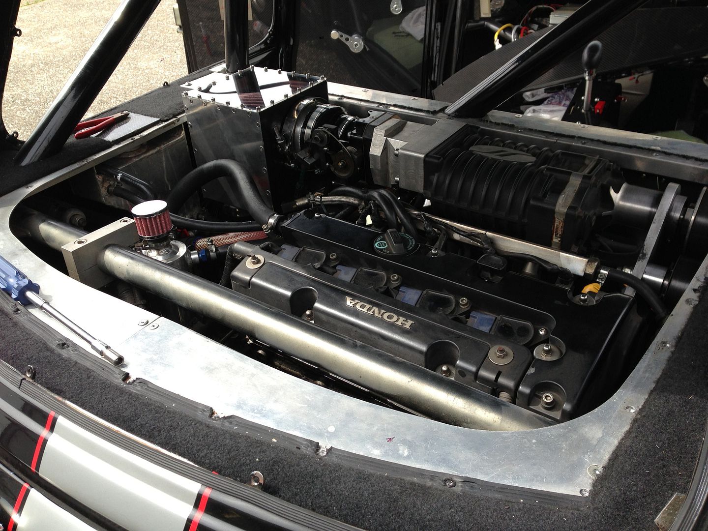
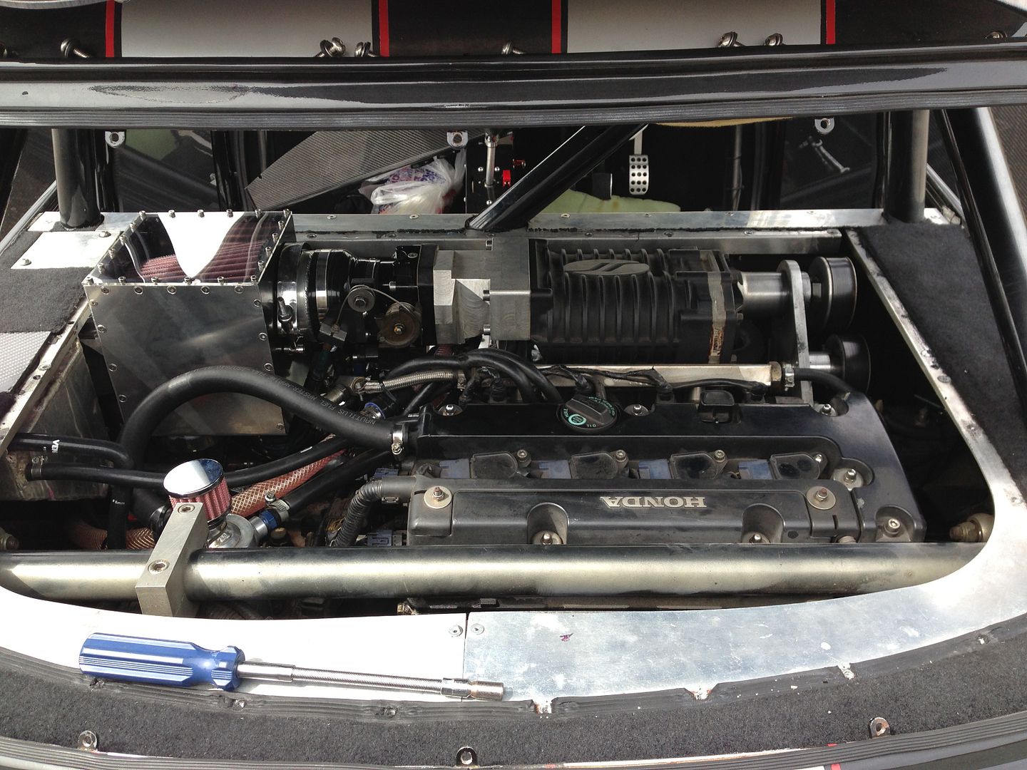
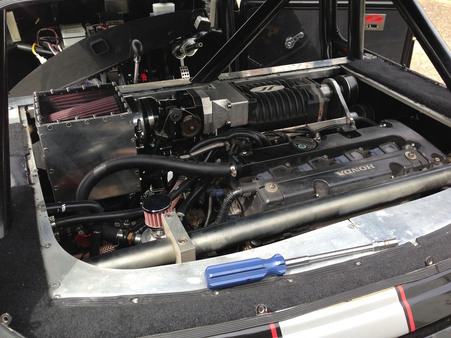
More work went on over the Bank Holiday weekend, I got it all back together and looking smart.


In my quest to get the air filter to fit in there I also had to:


Reposition the Fuel Pressure regulator

Rework the throttle cable holder

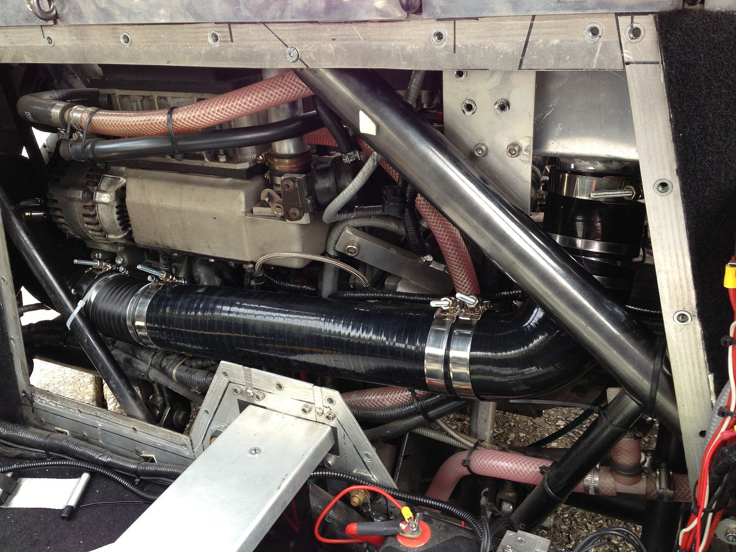
Change the pipe routing for the intercooler

Change the orientation of the Intake Air Control Valve (on the bottom of the throttle body) by 180deg

Reposition the MAP sensor onto the new IACV block


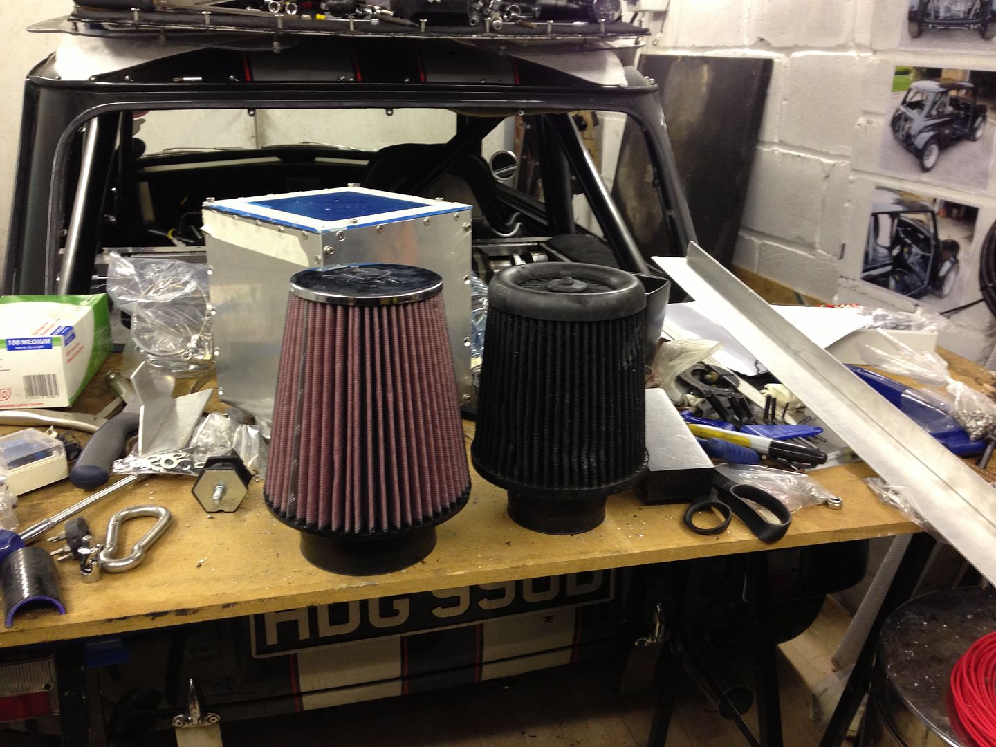
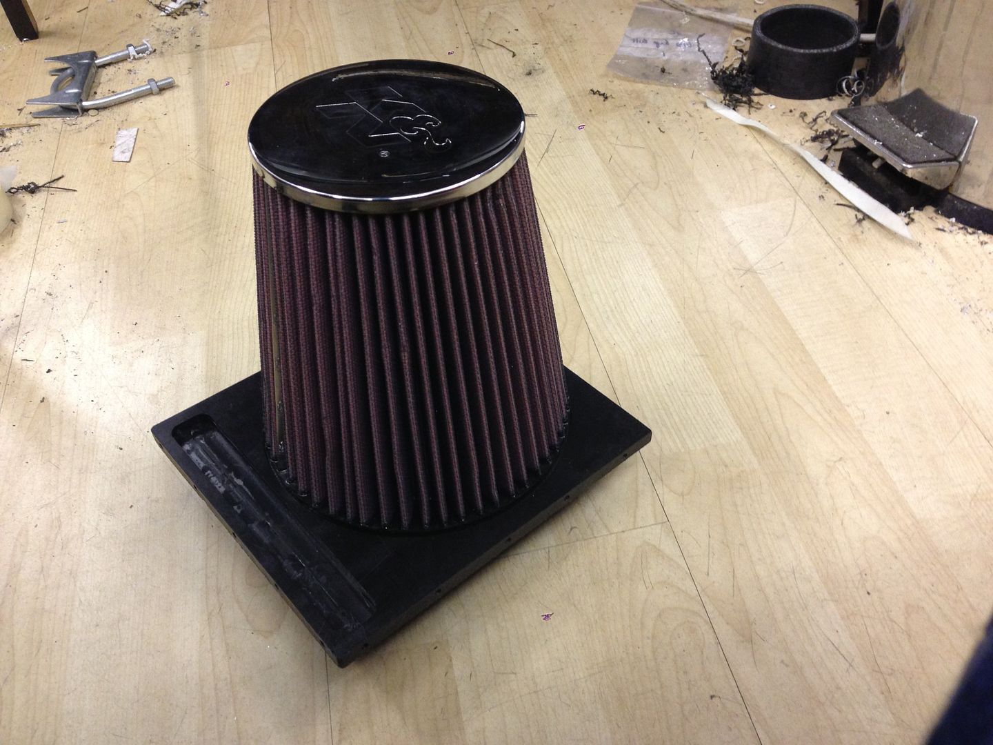
Old versus new air filters:


null_zpsobgtdowx.jpg


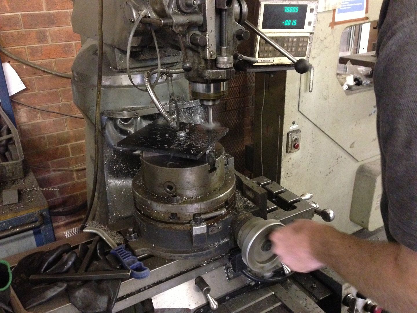
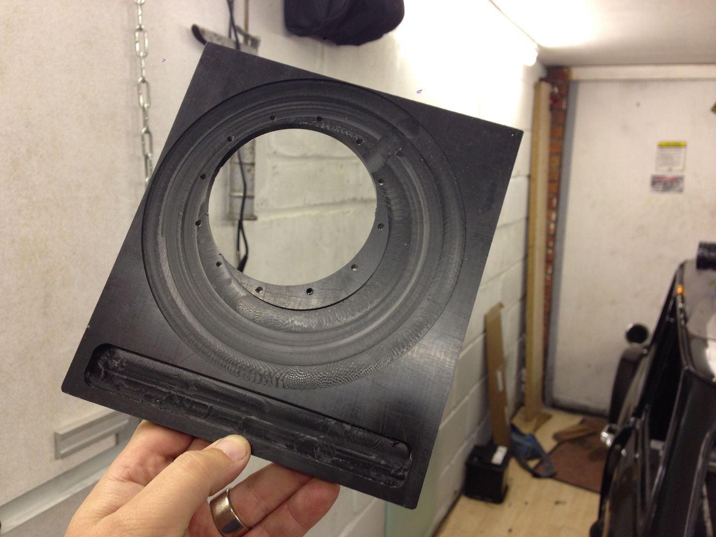
Stevie G and his massive mill making the recess for the large end of the filter to sit in:


null_zpsaafrjoh4.jpg


null_zps8yg4zt8l.jpg


null_zpsjmqxbwfy.jpg


null_zpsebob0srd.jpg


The odd shaped hole I needed to cut out of the air filter:


null_zps0dbr2o8k.jpg


Holes tapped in the acetal before adding the vee band connection:


null_zpsqzghyb2p.jpg


Vee Band Connection:


null_zpsaxl5encf.jpg


null_zpsdtbdrgvf.jpg


Filter in the housing:


null_zpsuosifc9t.jpg


Finally the Filter in place, note that the filter housing has its own 8mm exhaust bobbin support so the weight of it is not hanging off the end of the throttle body:


null_zpsv48d5sir.jpg


null_zpsriddj6de.jpg


null_zpsgcgfhbh6.jpg


null_zpsbrbks1yh.jpg


Here's the piping from the O/S:


null_zps9yerj3we.jpg


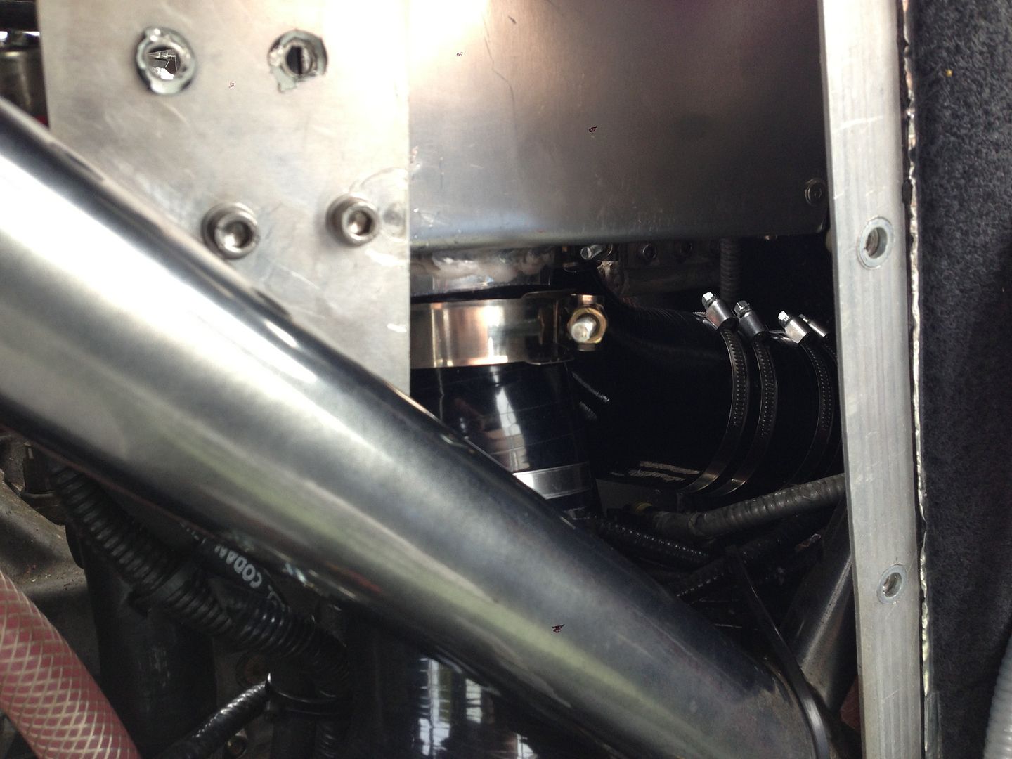
you can just see the piping to the N/S:


null_zps0qcwqb4b.jpg


#1013 FerritZA

FerritZA

    On The Road

  • Noobies
  • PipPip
  • 35 posts
  • Location: Cape Town
  • Local Club: MOCKZN

Posted 06 May 2015 - 09:57 AM

Those engine shots should be flagged as pornography.


#1014 MotorinFool

MotorinFool

    Stage One Kit Fitted

  • Noobies
  • PipPipPip
  • 61 posts
  • Location: WA
  • Local Club: Puget Sound Minis

Posted 06 May 2015 - 05:19 PM

Amazing!


#1015 cptkirk

cptkirk

    Camshaft & Stage Two Head

  • Members
  • PipPipPipPipPipPipPipPip
  • 1,799 posts
  • Location: West Sussex
  • Local Club: B.M.C. + Chiminiclub

Posted 07 May 2015 - 11:47 AM

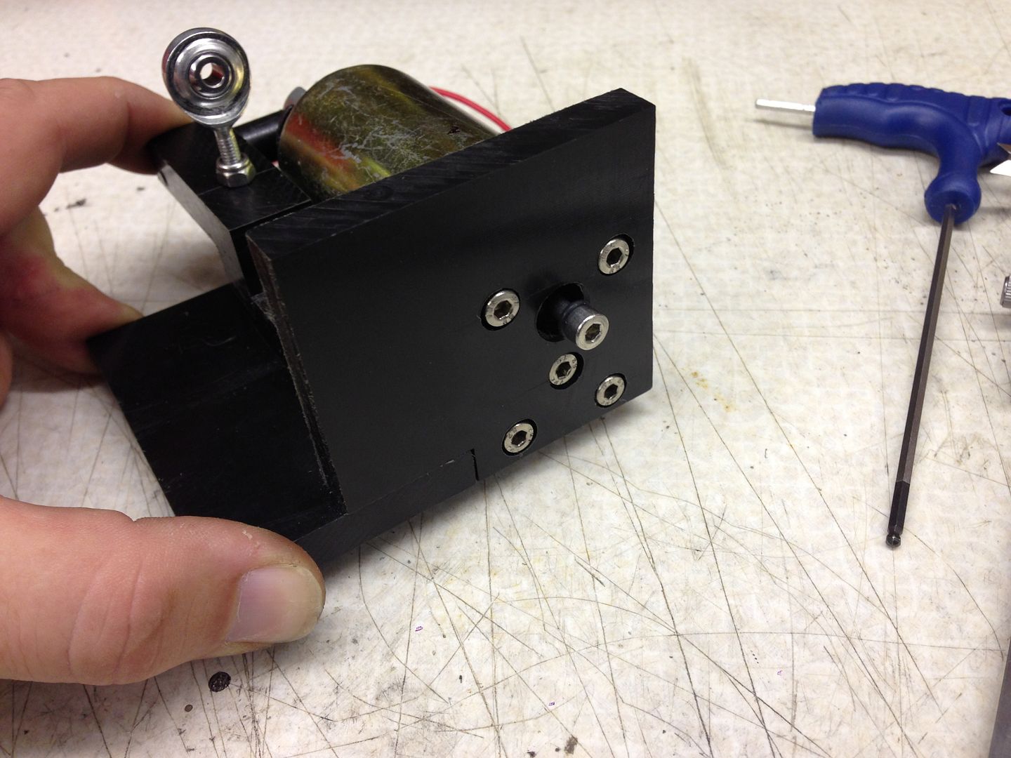
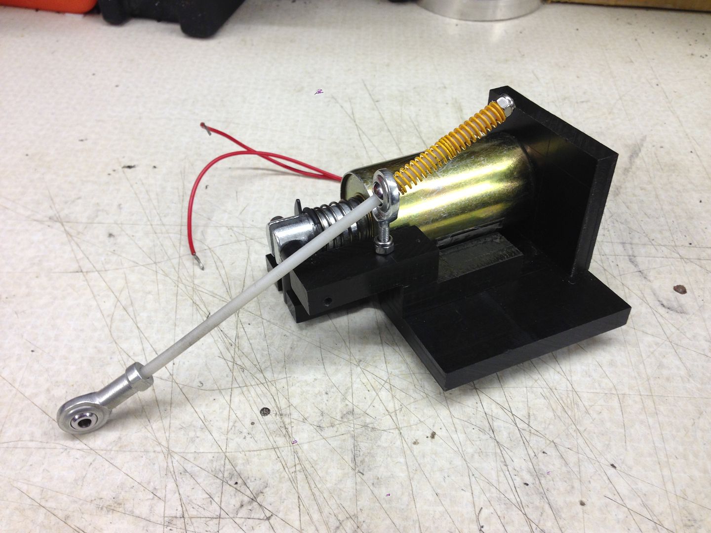
AUTOMATIC THROTTLE BLIPPER


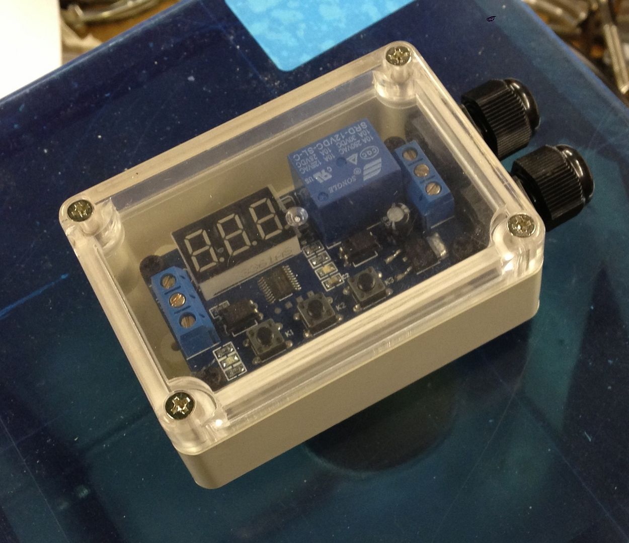
Made some ground with this, well I got the timer unit into its housing, still unsure where to mount it and whether to have a local switch (on the housing) or a remote switch (down on the tunnel with all the other switches).


I have got all the bits of acetal I need to start making the mounting plates so that will be next weeks project.


Not much to show, just the enclosure and the spring setup ready to go.


null_zpscixtnxkw.jpg


null_zps2qcx9mnh.jpg


#1016 dondo

dondo

    Mini Mad

  • Noobies
  • PipPipPipPip
  • 128 posts
  • Location: Glasgow

Posted 08 May 2015 - 08:33 AM

Again you have put us all to shame with your amazing engineering skills.


Edited by dondo, 08 May 2015 - 08:33 AM.


#1017 cptkirk

cptkirk

    Camshaft & Stage Two Head

  • Members
  • PipPipPipPipPipPipPipPip
  • 1,799 posts
  • Location: West Sussex
  • Local Club: B.M.C. + Chiminiclub

Posted 02 June 2015 - 08:05 AM

AUTOMATIC THROTTLE BLIPPER


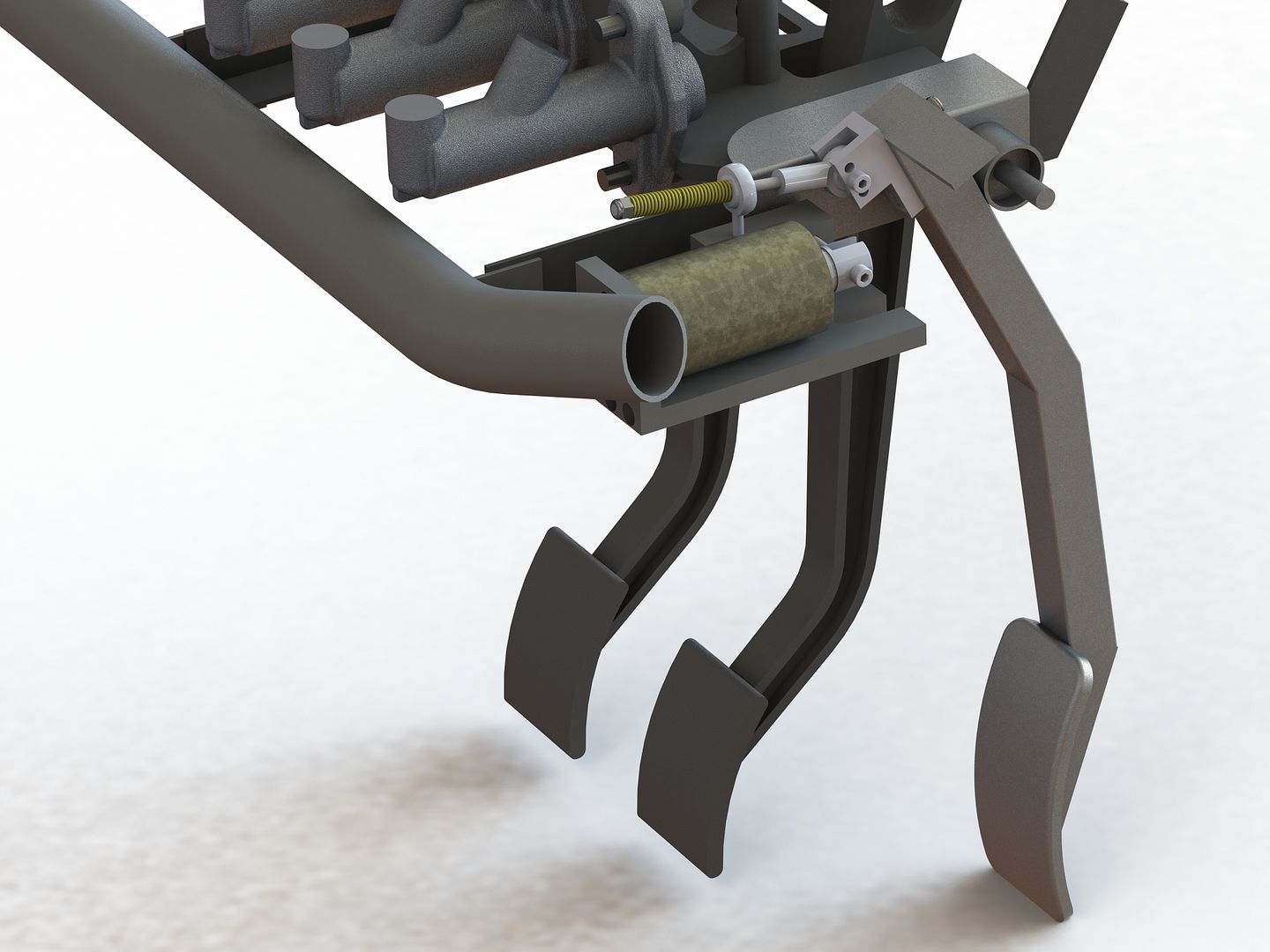
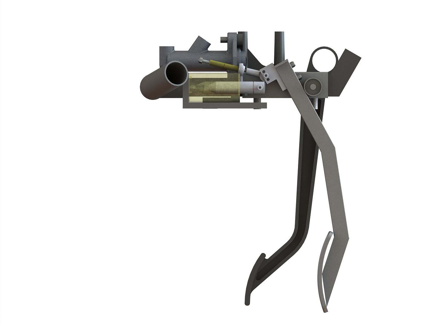
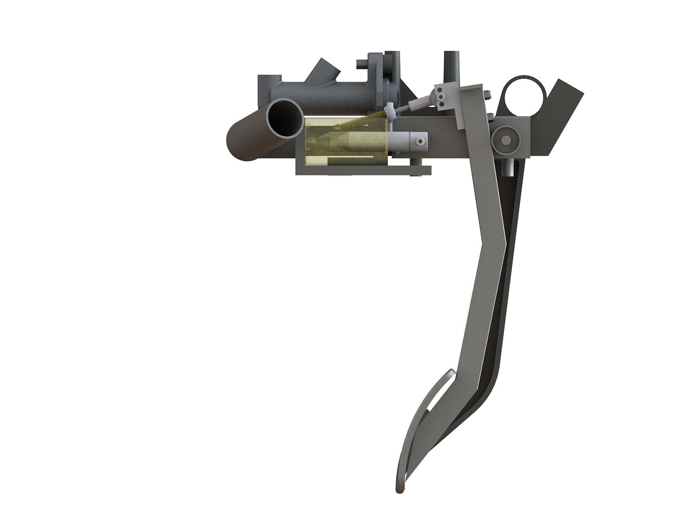
Slight change of direction on this, I made the executive decision that the 8mm bolt/spring arrangement was just complete overkill and that the stiffness of the springs wouldnt take any of the harshness out of the solenoid pull. I also didnt like the fact that you would be able to see the bolt/spring arrgt under the dash so I went and re-designed the the whole thing to use a 4mm ID spring and relative M4 fittings. This in itself has proved challenging as when you order 4mm rod it seems to come in sizes ranging from 4.0 (stainless) to 4.4 (acetal) and after failing to get a thread on the stainless rod I was forced to reduce the OD of the acetal rod by using a drill and some sand paper. There are renders of the recent modelling below.


I recenlty purchased a cross vice to use with my pillar drill to make it into a ghetto milling machine, which although it still needs some refinement is giving some half decent results. I dont need 0.1mm accuracy for these little bits, so it does me fine for now.....


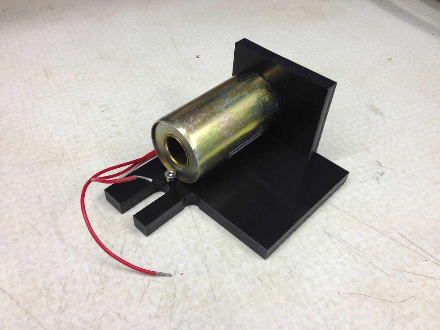
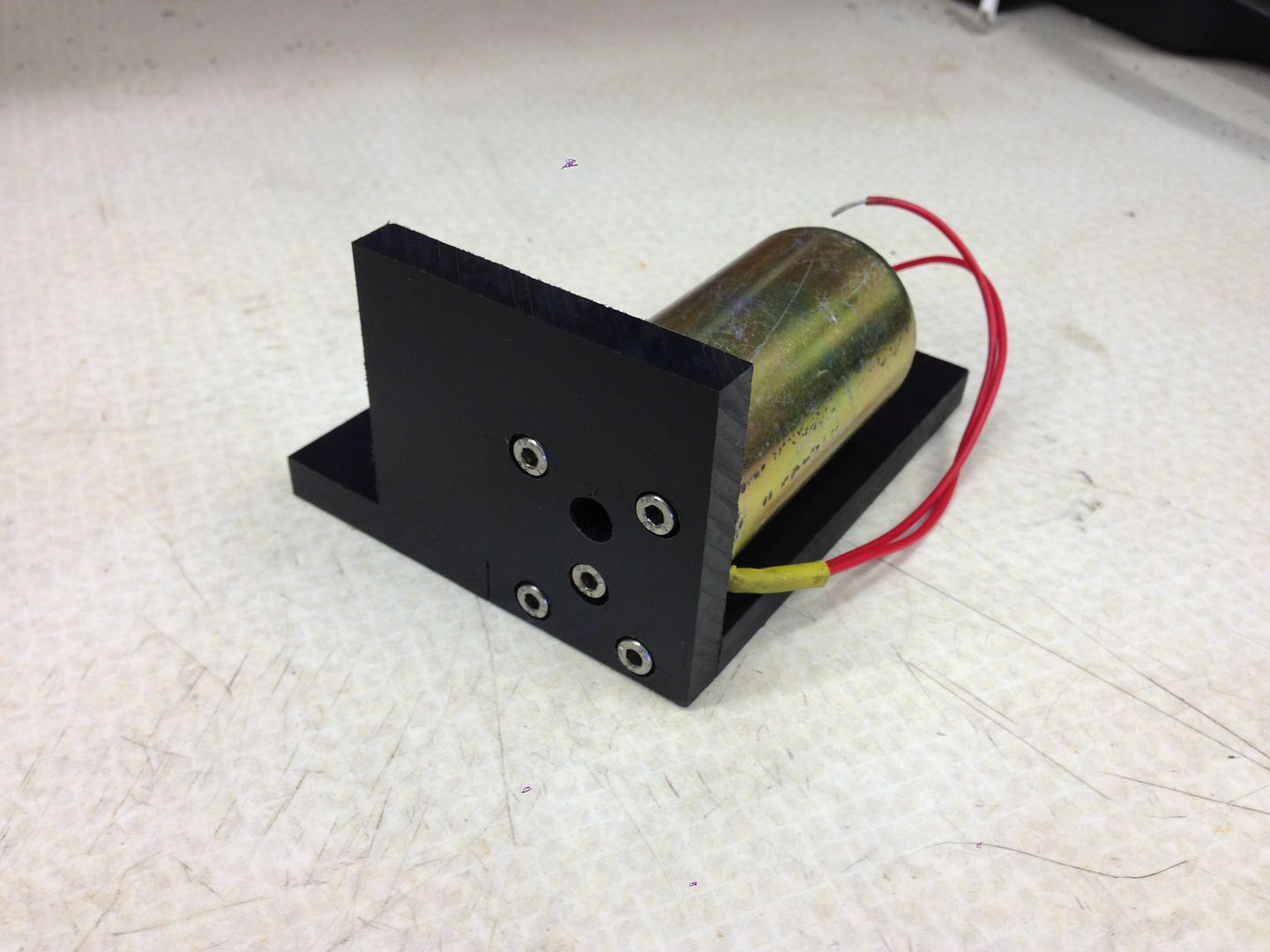
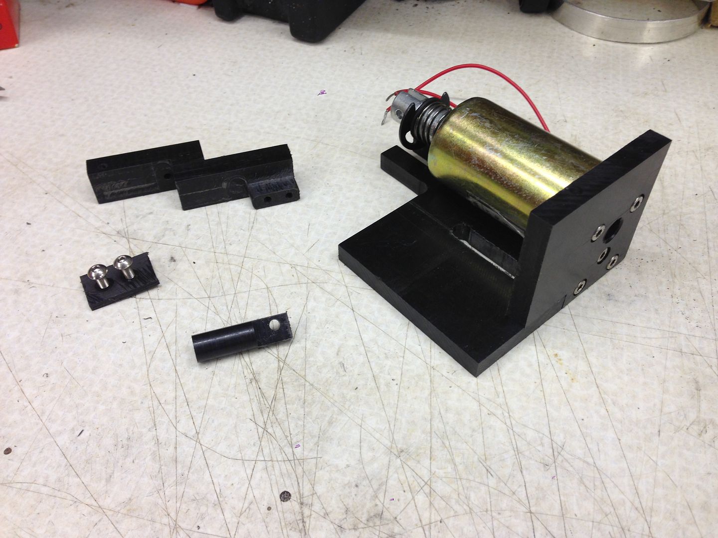
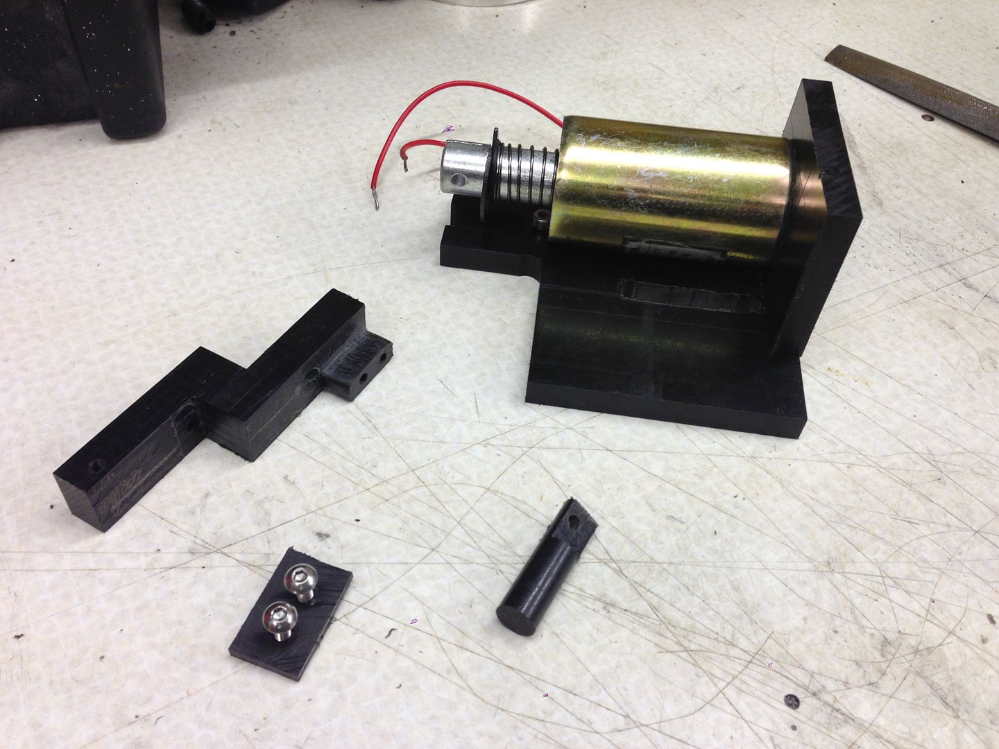
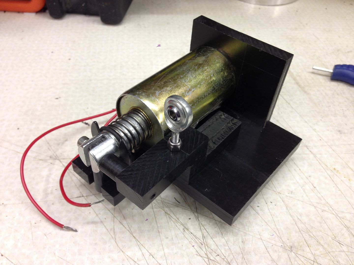
So with some acetal sheet purchased I set about making the housing/sliding mechanism, of which you can see the photos below.


This view shows the new design, note in this view the solenoid is activated.


THROTTLE%20BLIPPER%20009_zpstv2wqe1s.jpg


This view show the throttle pdel is depressed but the solenoid isnt activated:


THROTTLE%20BLIPPER%20006_zpscg3llm7w.jpg


This one shows the throttle pedal at rest:


THROTTLE%20BLIPPER%20007_zpsxyny2rbm.jpg


Here are a few snaps of the housing/sliding mechanism:


null_zpsfeki9pub.jpg


null_zps1byy3bzo.jpg


null_zps40v5kv9y.jpg


null_zps9vqdulqe.jpg


null_zpshdtp3arf.jpg


null_zpsyjpsktng.jpg


null_zpsufkiql2k.jpg


#1018 RED HOT

RED HOT

    Fantasy F1 Winner 2011

  • Traders
  • PipPipPipPipPip
  • 354 posts

Posted 10 June 2015 - 08:38 AM

I love the detail you go into with your renders etc. I have to make do with 2d cad and then just hope my measuring sticks haven't lied to me!


One question though, why did you decide to mount it to the pedal assy rather than to the throttle body directly?


#1019 cptkirk

cptkirk

    Camshaft & Stage Two Head

  • Members
  • PipPipPipPipPipPipPipPip
  • 1,799 posts
  • Location: West Sussex
  • Local Club: B.M.C. + Chiminiclub

Posted 10 June 2015 - 09:50 AM

I love the detail you go into with your renders etc. I have to make do with 2d cad and then just hope my measuring sticks haven't lied to me!


One question though, why did you decide to mount it to the pedal assy rather than to the throttle body directly?


Quite simply it was a space issue, the solenoid is 40mm diameter and about 95mm long, so trying to find somewhere for it to sit in that engine bay (next to the throttle body, with a strong enough mounting structure) was going to be a squeeze. Trust me when I say I've thought long and hard about ways to get it into the engine bay.


In an ideal world I would have the solenoid acting on the TB end of the TB outer cable (where the nuts are to hold the cable end in place), this way the throttle pedal would remain still at all times and you dont run the risk of the cable coming off the throttle body if you were to just have the solenoid acting on the throttle body cable holder.


What I am currently creating will probably be the first iteration of many to come. I am already thinking of linear actuator with a raspberry Pi or other PLC, linked to speed sensors/revs to effect realtime rev matching, although with this recent round of upgrades I have promised to ease off for a bit with spending on the car.


#1020 RED HOT

RED HOT

    Fantasy F1 Winner 2011

  • Traders
  • PipPipPipPipPip
  • 354 posts

Posted 10 June 2015 - 10:01 AM

I thought it might be a space restriction issue, it does look rather tight around that area! Looking forward to the next update.


2 user(s) are reading this topic

0 members, 2 guests, 0 anonymous users