Supercharged K20a2 Vtec - Race Spec
#781
Posted 14 March 2012 - 08:25 AM
1) Crank Pulley replaced.
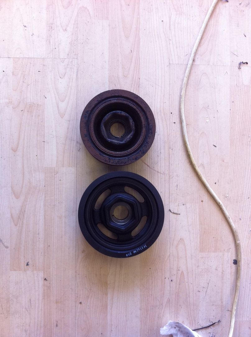
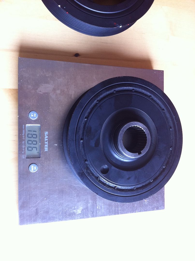
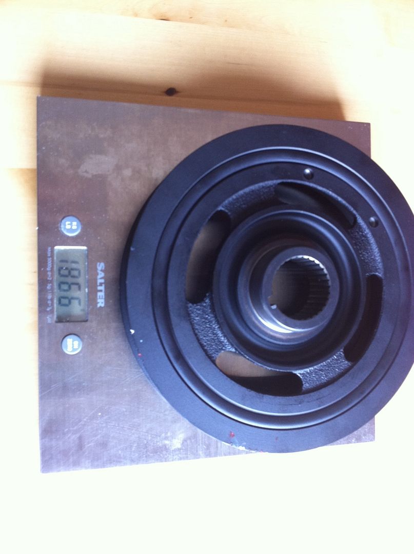
Before I put the new pulley on I decided to weigh it, more out of curiosity thatn anything else and the results were really quite surprising. Below is a photo of the two next to one another and then them seperately on the scales.
K20 original:
K24 6.37":
Yes thats right, 20g's lighter and considerably bigger.
2) Snout Clamp
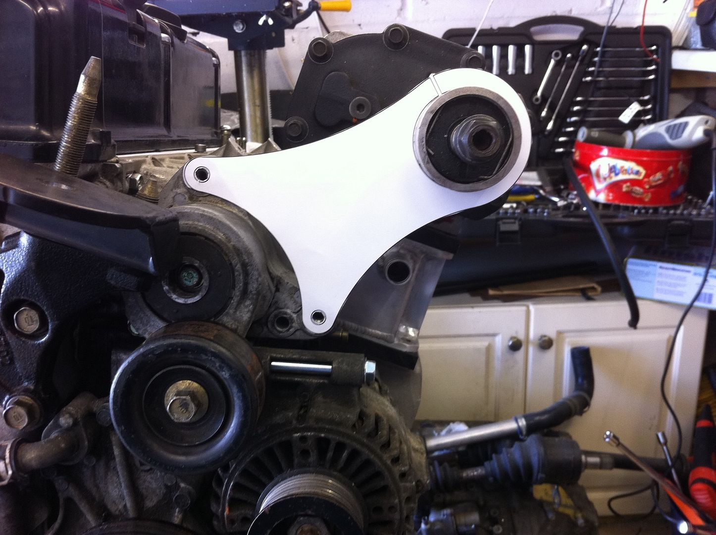
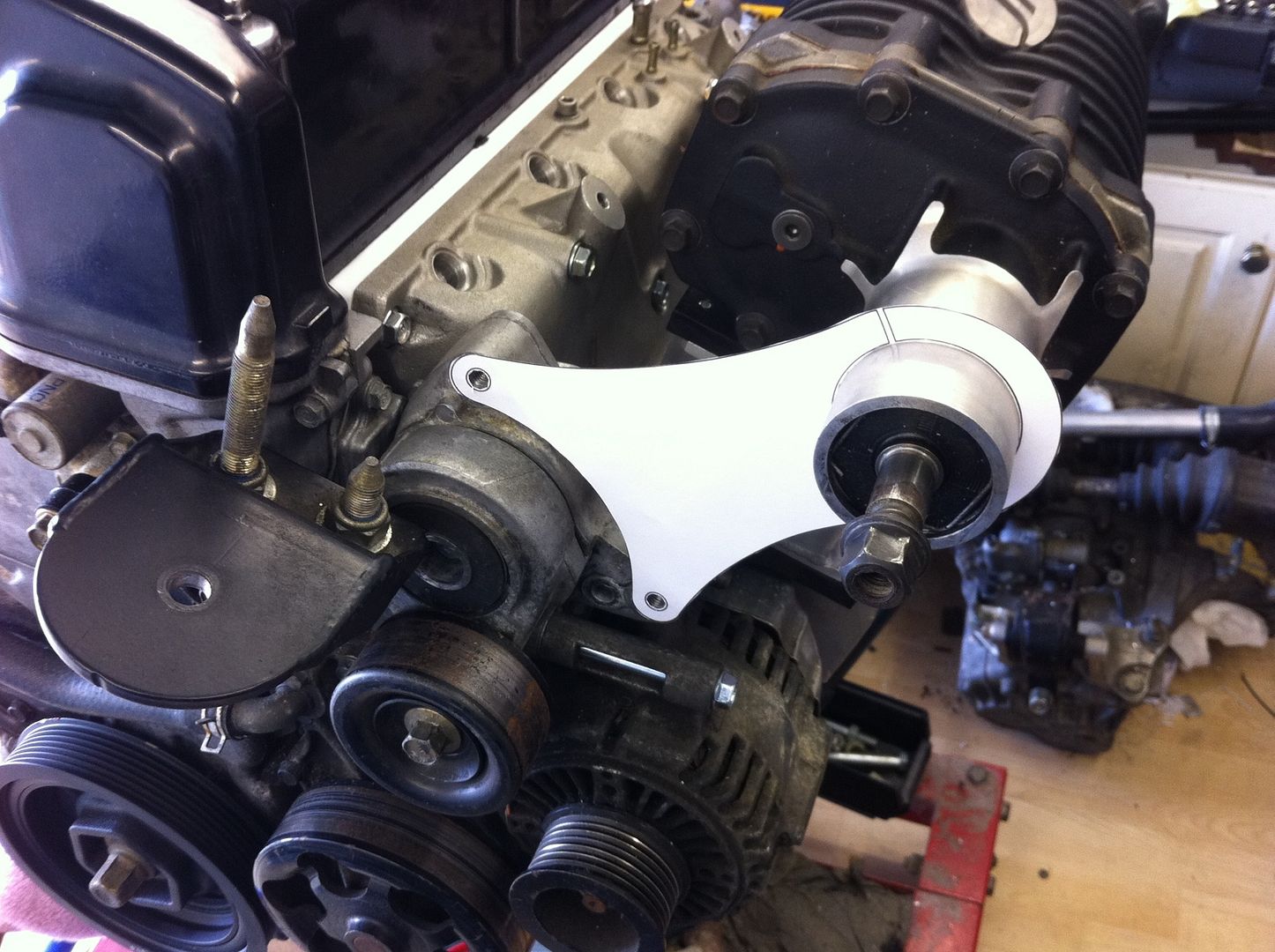
I offered up a paper template of the latest and simplest design, pretty close, just a couple of mm adjustment and we are there.
3) Thermal Gasket
I got a better photo of the new PTFE Thermal Gasket when I pulled the charger off the motor again.
#782
Posted 17 March 2012 - 09:13 AM
#783
Posted 23 March 2012 - 11:31 PM
#784
Posted 24 March 2012 - 04:54 PM
Might be an odd question but what is happening at RAF Marham? My brother is posted there at the moment...?
Theres a track day happening there on the last weekend in April.
#785
Posted 24 March 2012 - 05:34 PM
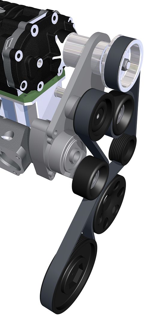
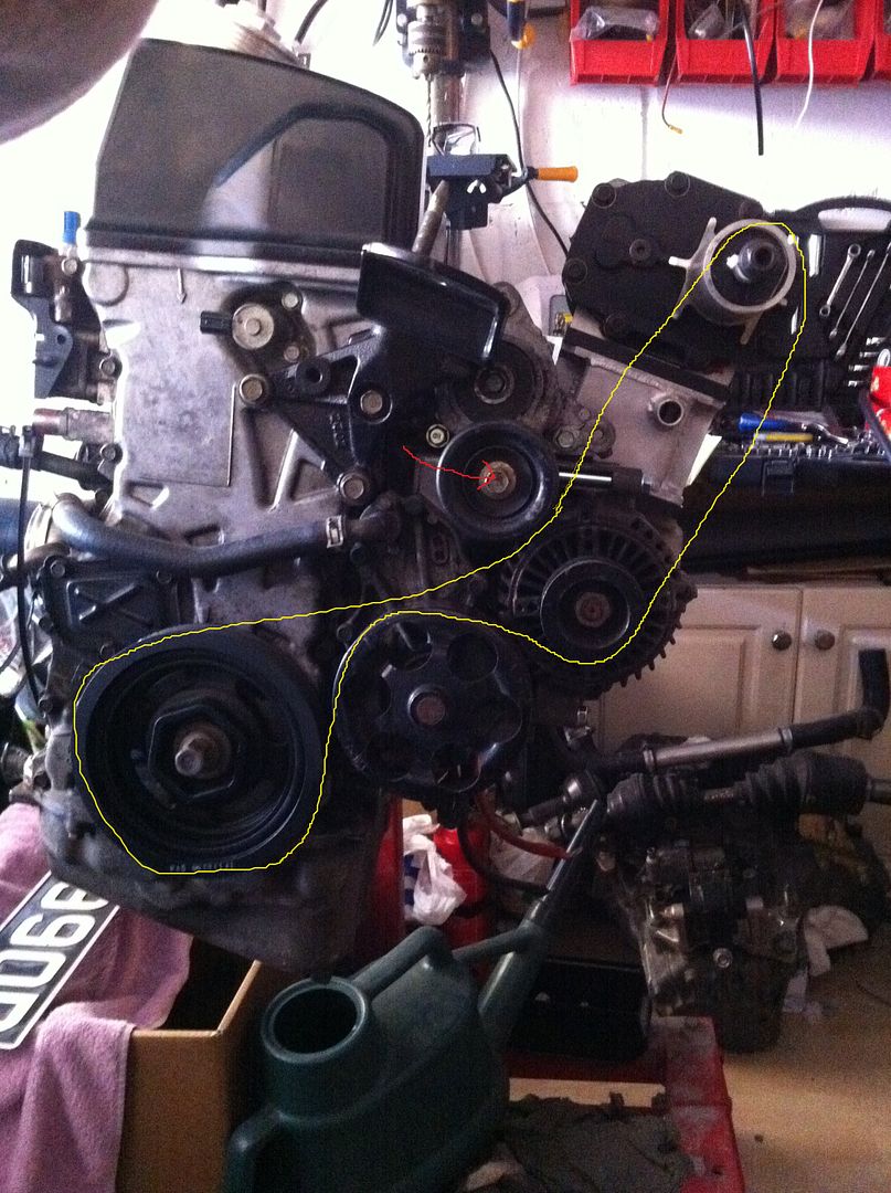
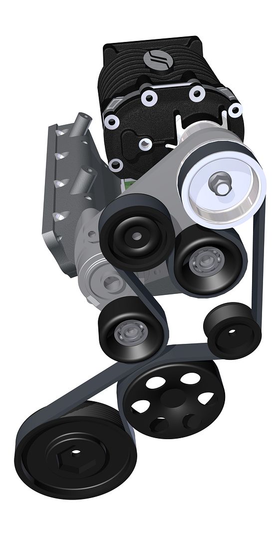
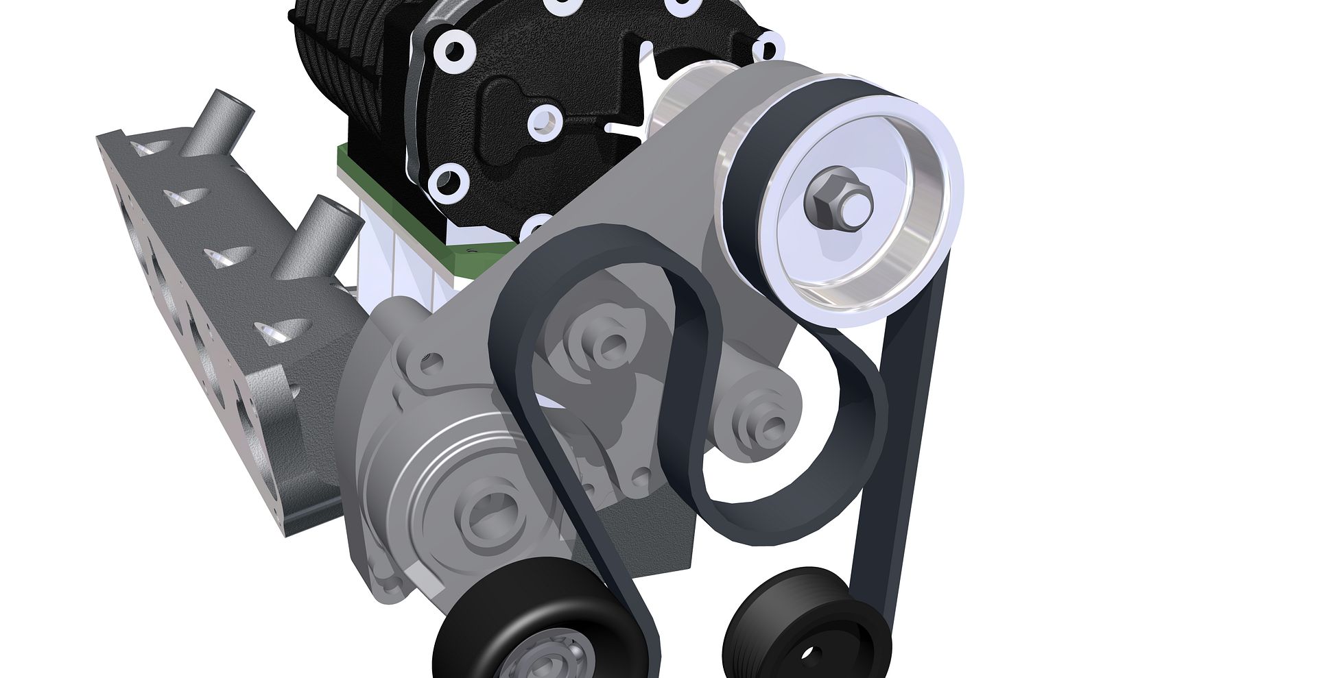
I now have a new design for the belt routing which incorporates the latest revision of the snout clamp (version No.11).
I am going to be using the OEM grooved idler pulley that is used on the EP3 Civic and will be using another smooth tensioner, the same as in use on the auto tensioner. I have drawn up 2D pulley layouts as was suffering with what appeared to be belt stretch and wanted to know how effective the auto tensioner was in its current configuration compared to the OEM setup. I drew two setups, measuring the theoretical belt length, one with the tensioner completely off and one with it as it would be without a belt (fully on). So my current setup on had a difference of 21mm in belt length, hence it being a b1tch to get on and n ot able to keep the tension very well, compared to the OEM setup that had 60mm difference in belt length. As an added bonus it has increased the amount of wrap on the supercharger pulley by a considerable amount, very happy.
I have the plate and billet rod sat here waiting to be machined and should be able to get the turning done in the week and the mill work next week. Bring on the light nights so I can work on the car.
For those that are interested I did a few renders of what the new setup will look like:
Heres what the current setup route would be, the red arrow shows how the tension goes on to the belt:
Heres the new setup:
One showing the new snout clamp/pulley mount
#786
Posted 24 March 2012 - 05:44 PM
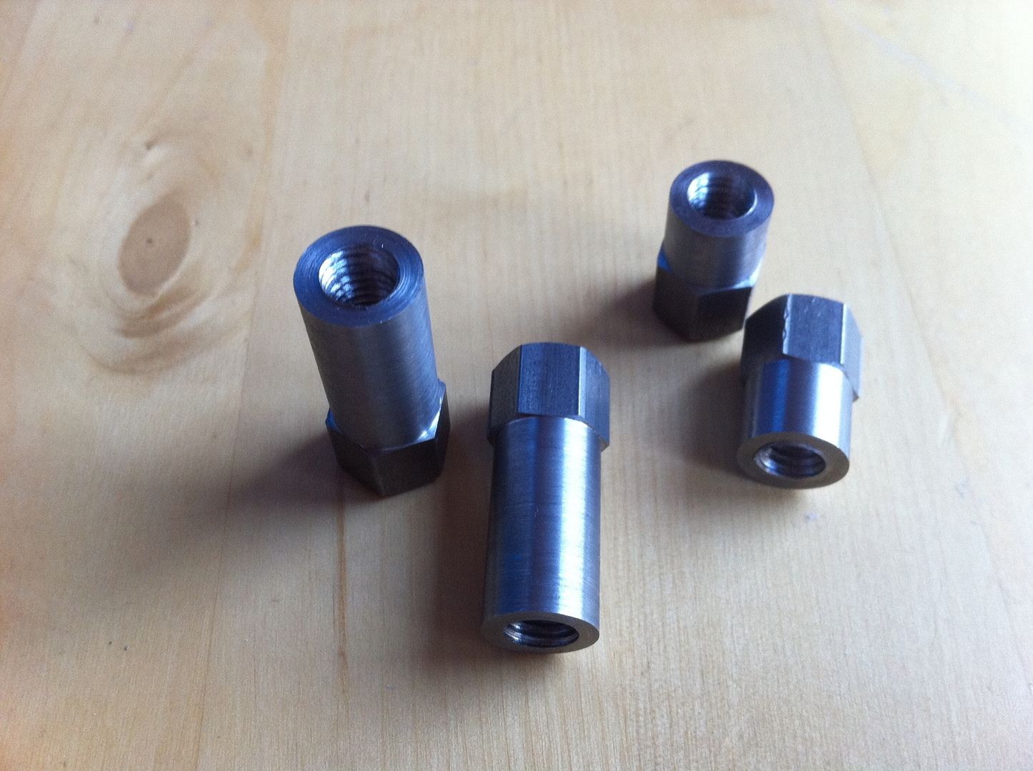
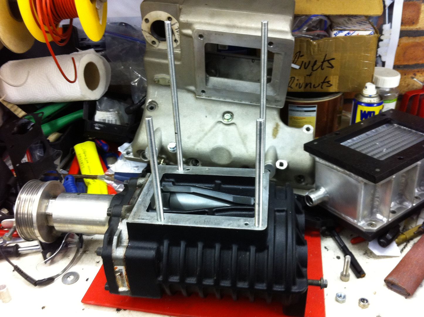
They are to go on the end of these:
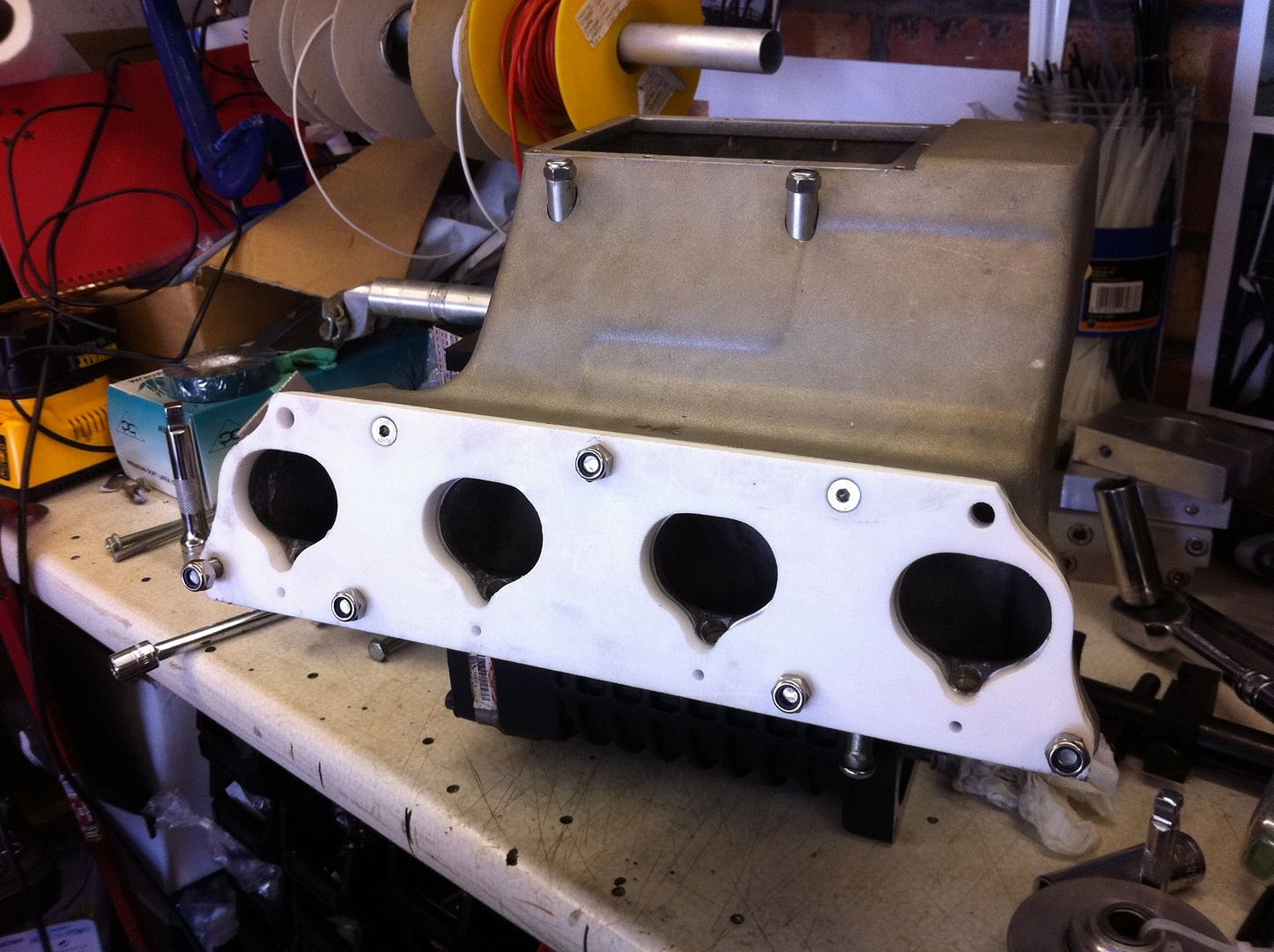
To replace the ones you can see in this shot and the two that sit inside the intake manifold:
#787
Posted 24 March 2012 - 09:13 PM
just thinking it would save having so many pullys
Andy
ps looking good
#788
Posted 03 April 2012 - 08:38 AM
is it not possible to have the belt runnning from the alternator around the top of tensinor then up to the supercharger then down to the crank ? but will have to have a tensioner pushing the other way, or does this not use up enough of the belt?
just thinking it would save having so many pullys
Andy
ps looking good
Hi Andy, long time.
I see what you're saying but making the auto tensioner work the opposite way is a proper mission. If my drawings are correct this way should work a treat and the two extra pullies arent going to lose me much power.
Cheers
#789
Posted 03 April 2012 - 08:47 AM
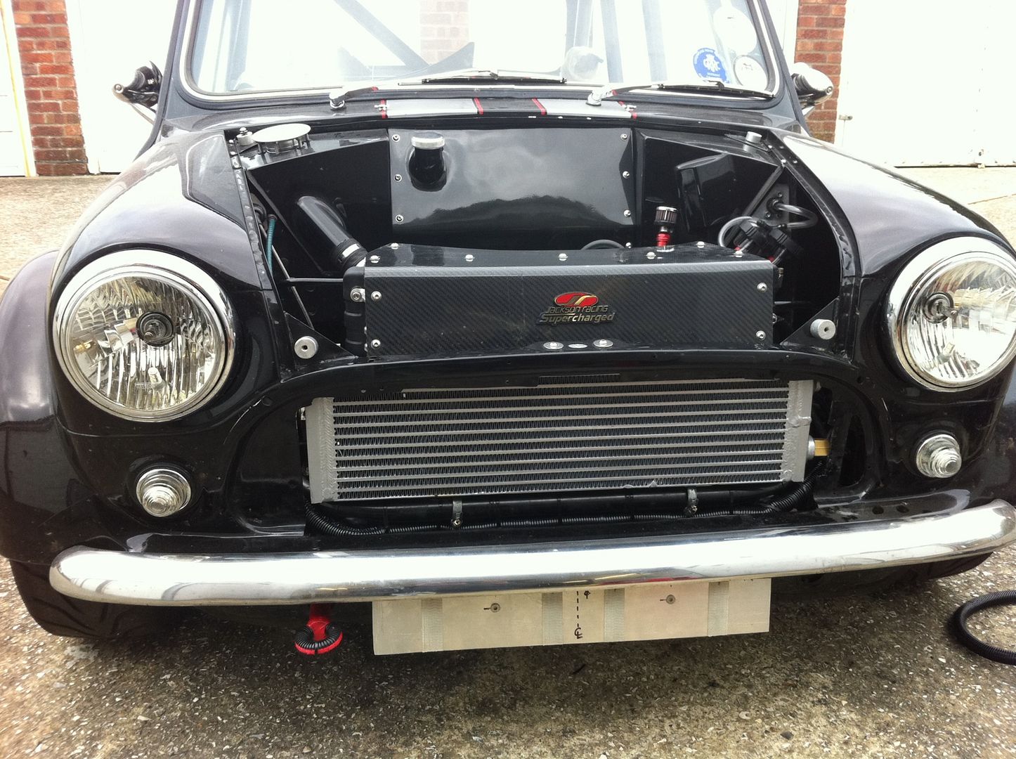
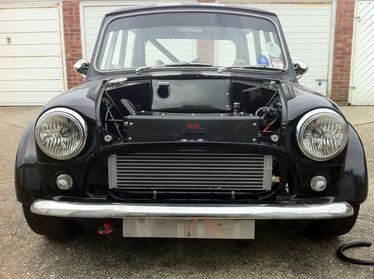
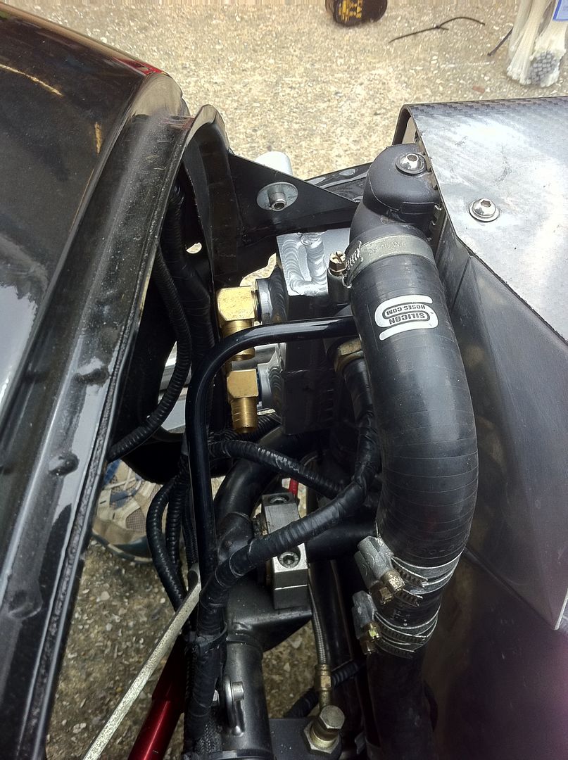
I got my pre rad fully fitted into place on saturday, proper chuffed with it, I even got the grille back on and it only fouls a tiny amount, not that anyone would ever notice, unfortunately I dint get any with the grille on but I will in the near future.
I am going to see what the engine temps are like before I decide if I need anymore cool air ducting past the pre rad into the engine rad.
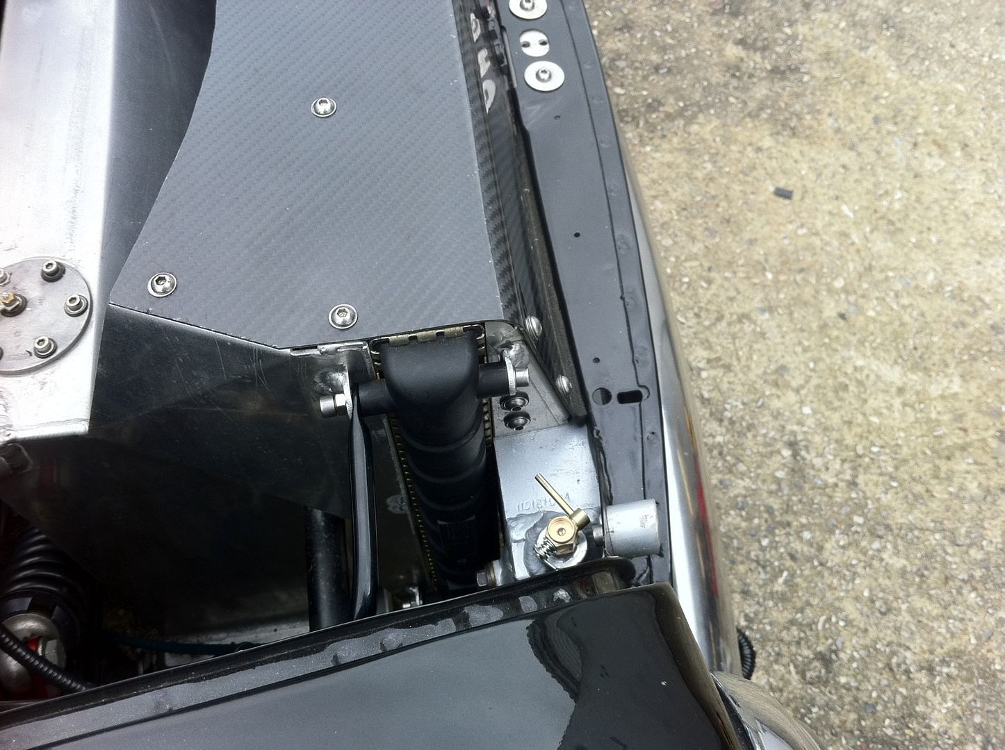
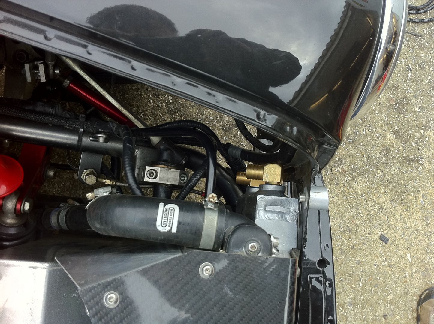
I ended up with the pre rad upside down to its normal usage position, this might sound odd but it has worked out for the best as its drainage plug is now a bleed screw, perfectly placed to get rid of any air in the system at the top on the drivers side of the rad. By jacking the beast up on the drivers side whilst bleeding out the air will totally get rid of any air in the rad.
I havent got it piped yet as I was waiting til I put the engine back in so I have it on ramps to fit the pipework.
A few photos of it installed:
#790
Posted 05 April 2012 - 08:31 AM
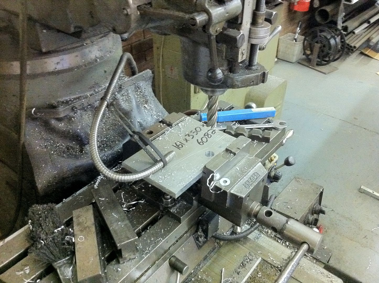
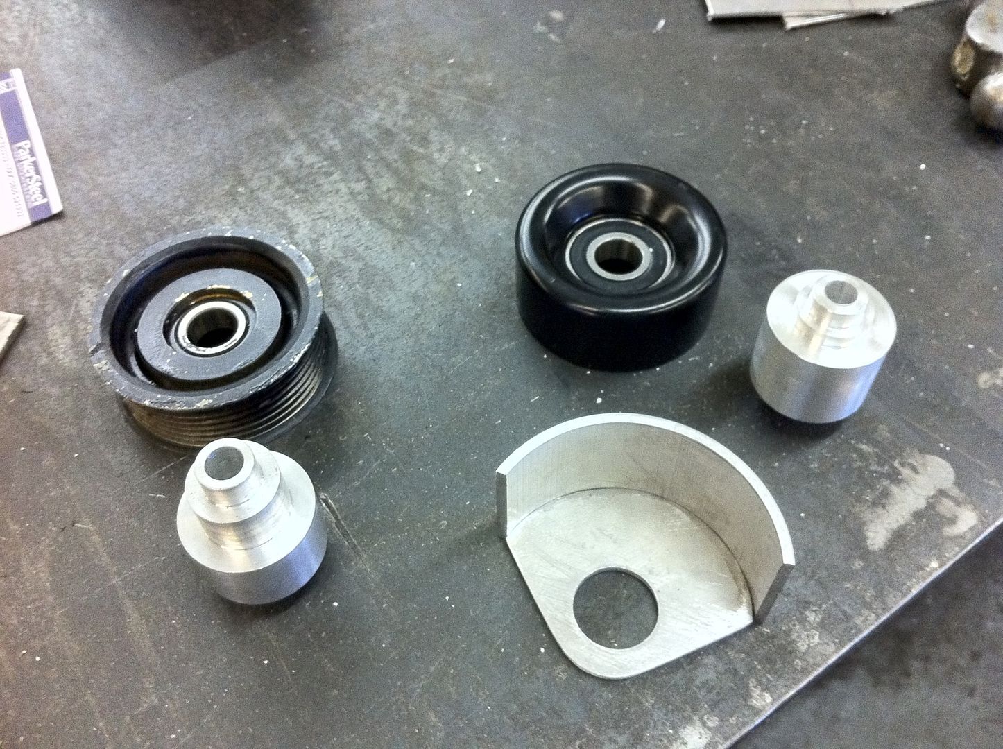
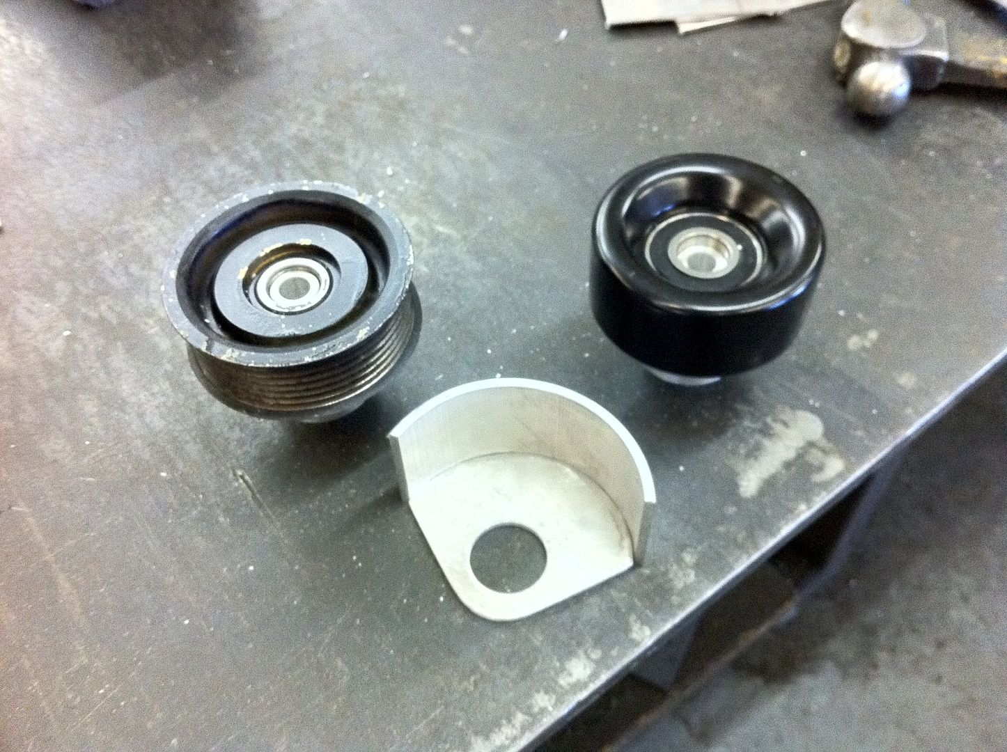
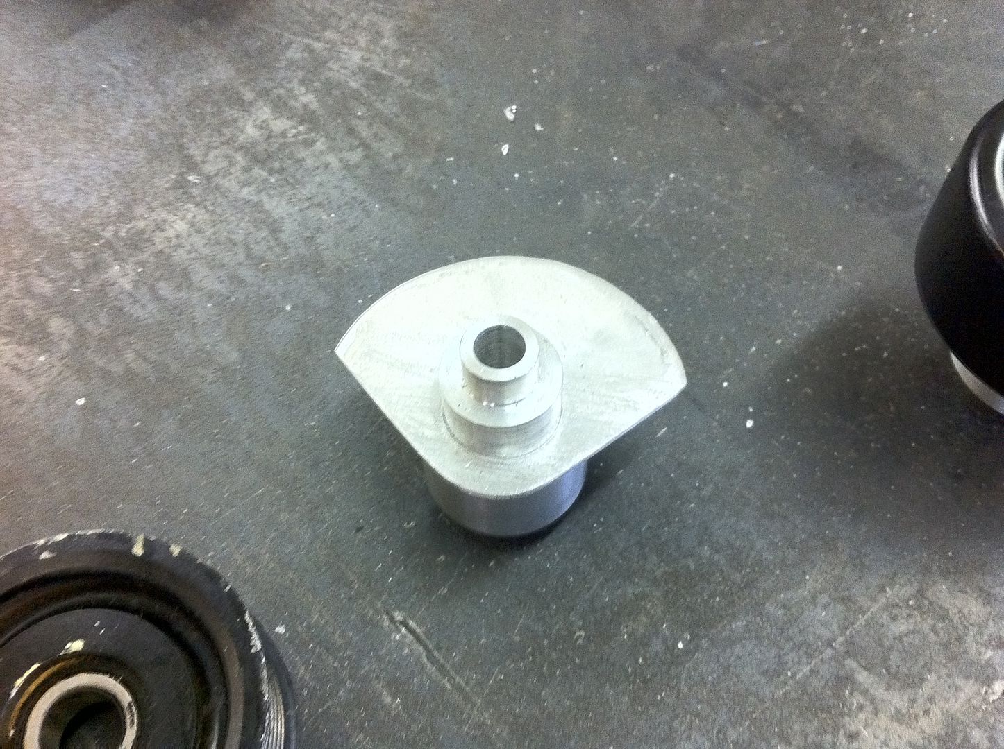
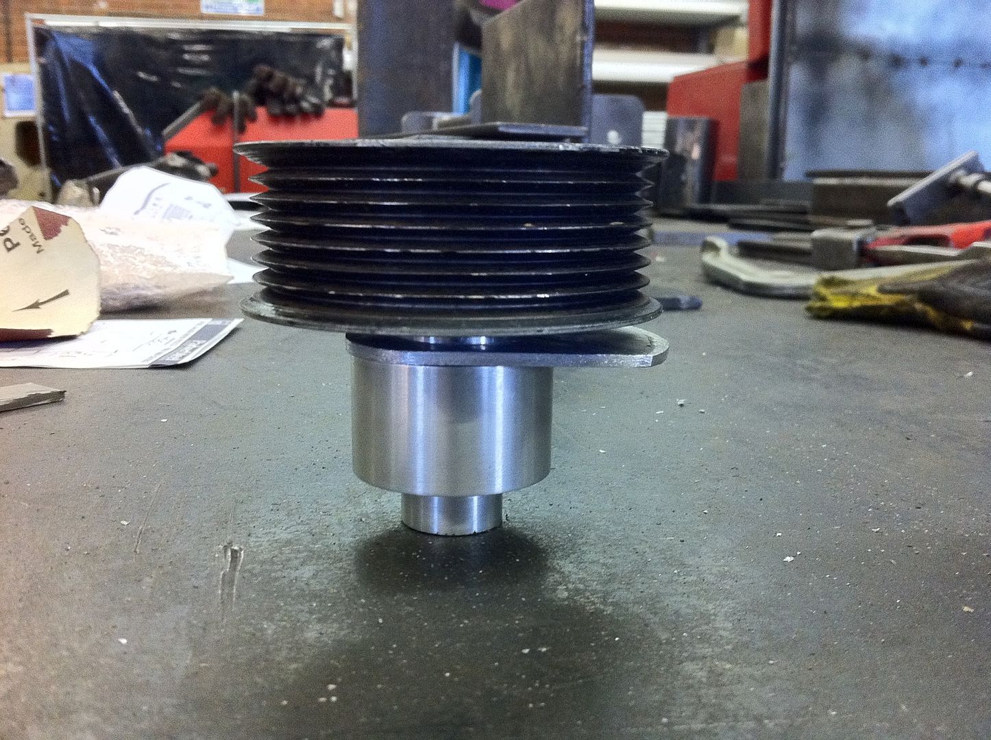
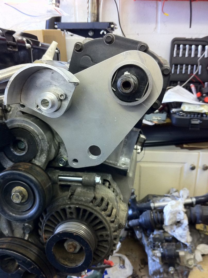
Myself and my good mate Stevie G started on creating the snout clamp last night, its so much easier when you have all the right tools for the job. I left steve doing the milling whilst I made the little pulley cover. Unfortunately the only photo I have of the snout clamp is early on when the holes are being drilled, however with the Easter weekend upon us there will be a lot of progress by Tuesday and I will keep everyone updated.
Over the last couple of weeks my other good mate Jim Bright has been doing some turning for me on his lathe, making the fixings for the two extra pulleys that you can see in the photos below.
Snout clamp in the mill:
Pulleys, mounts and covers:
#791
Posted 08 April 2012 - 05:52 AM
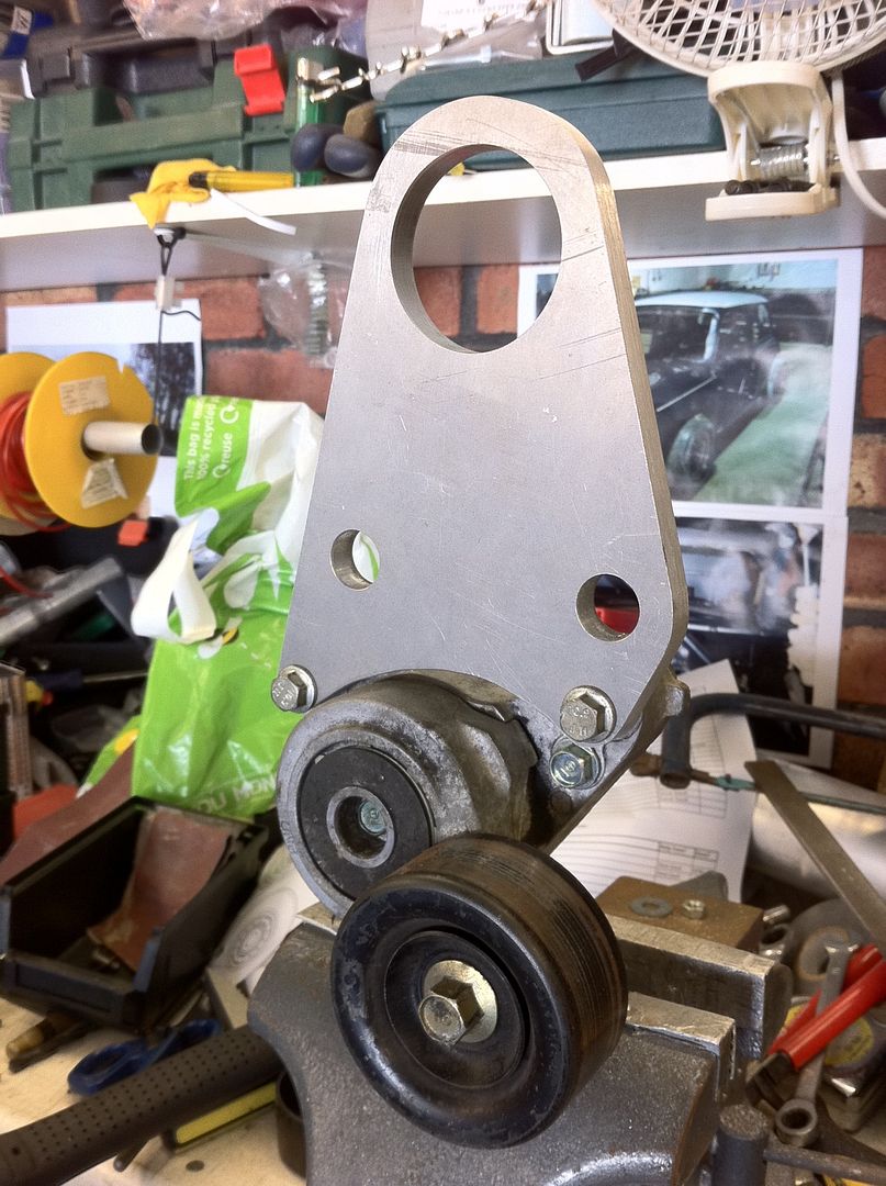
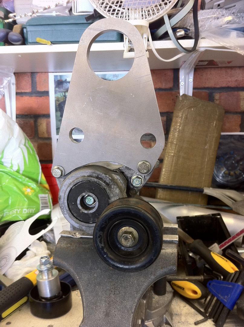
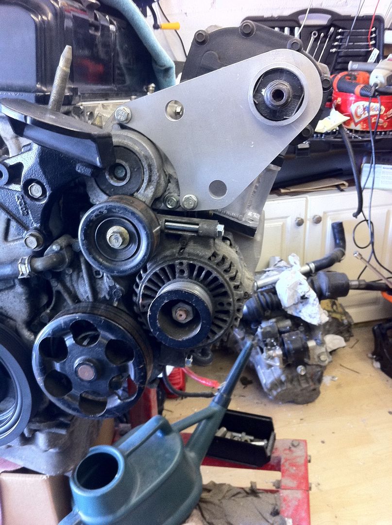
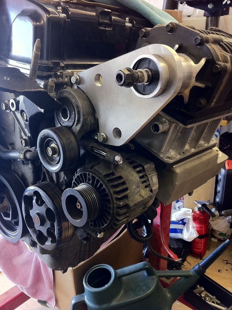
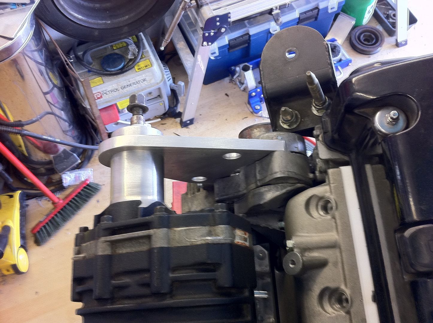
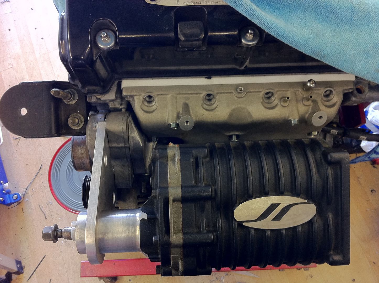
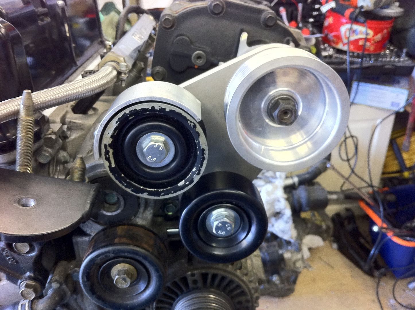
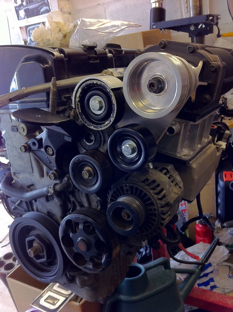
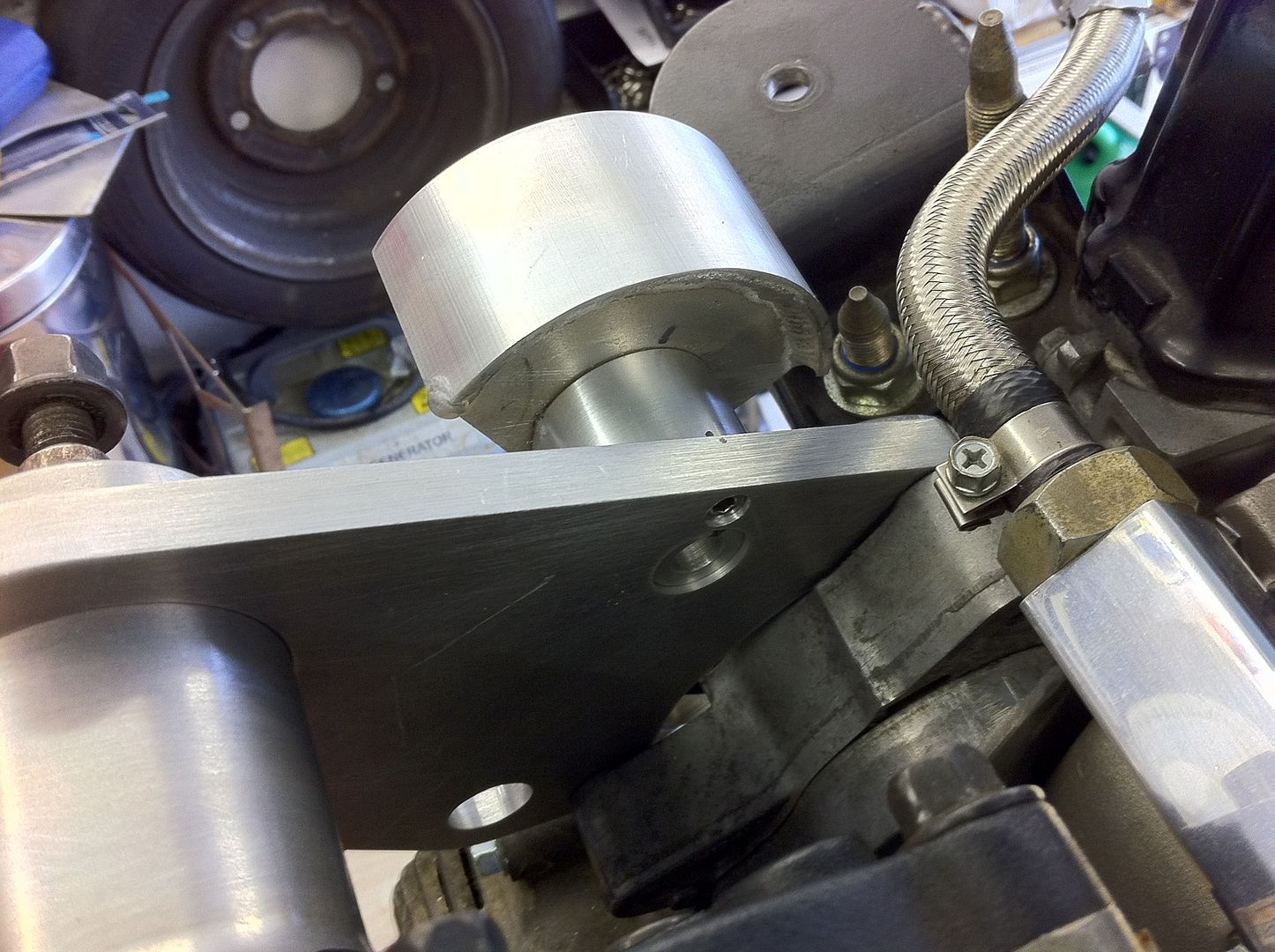
First trail fit of the clamp on the auto tensioner to make sure holes line up.
It took a bit of gentle sanding and a bit of persuasion to get it on the snout but then as I ended up with a design that isnt a true clamp then that it exactly what I needed, a slight interference fit.....
Then I fitted all the pulleys and relative fittings to the clamp plate.
#792
Posted 08 April 2012 - 09:09 AM
#793
Posted 08 April 2012 - 10:14 AM
#794
Posted 08 April 2012 - 12:16 PM
nice
Thanks Martin..
That's looking sweet.
Cheers Birdman..
#795
Posted 10 April 2012 - 08:02 AM
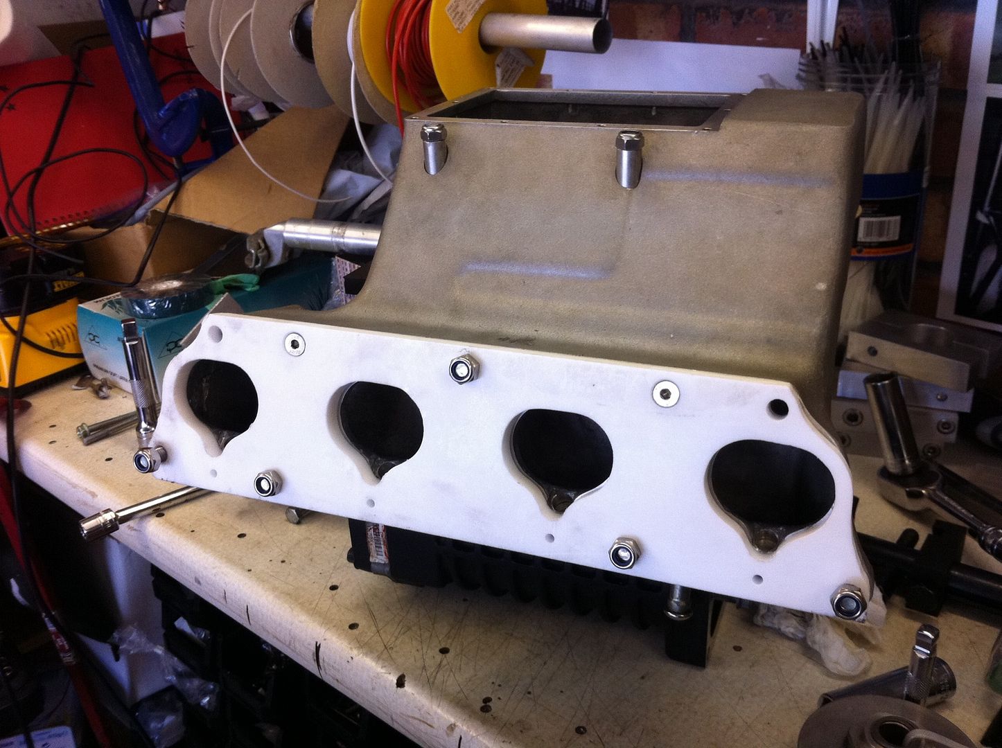
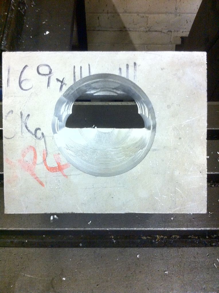
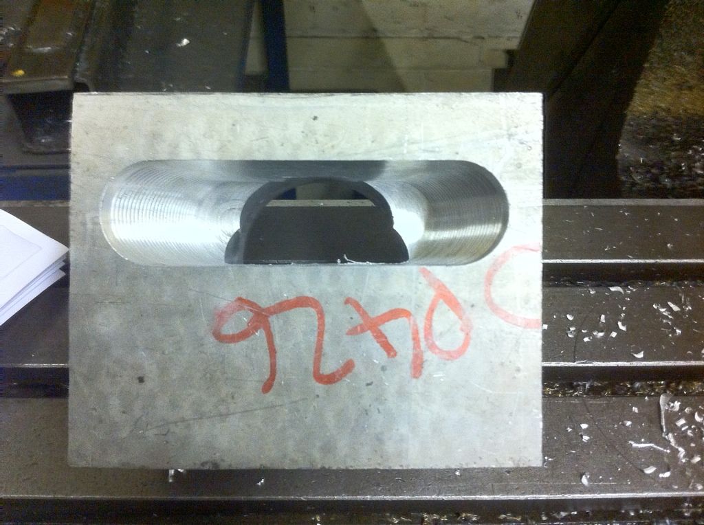
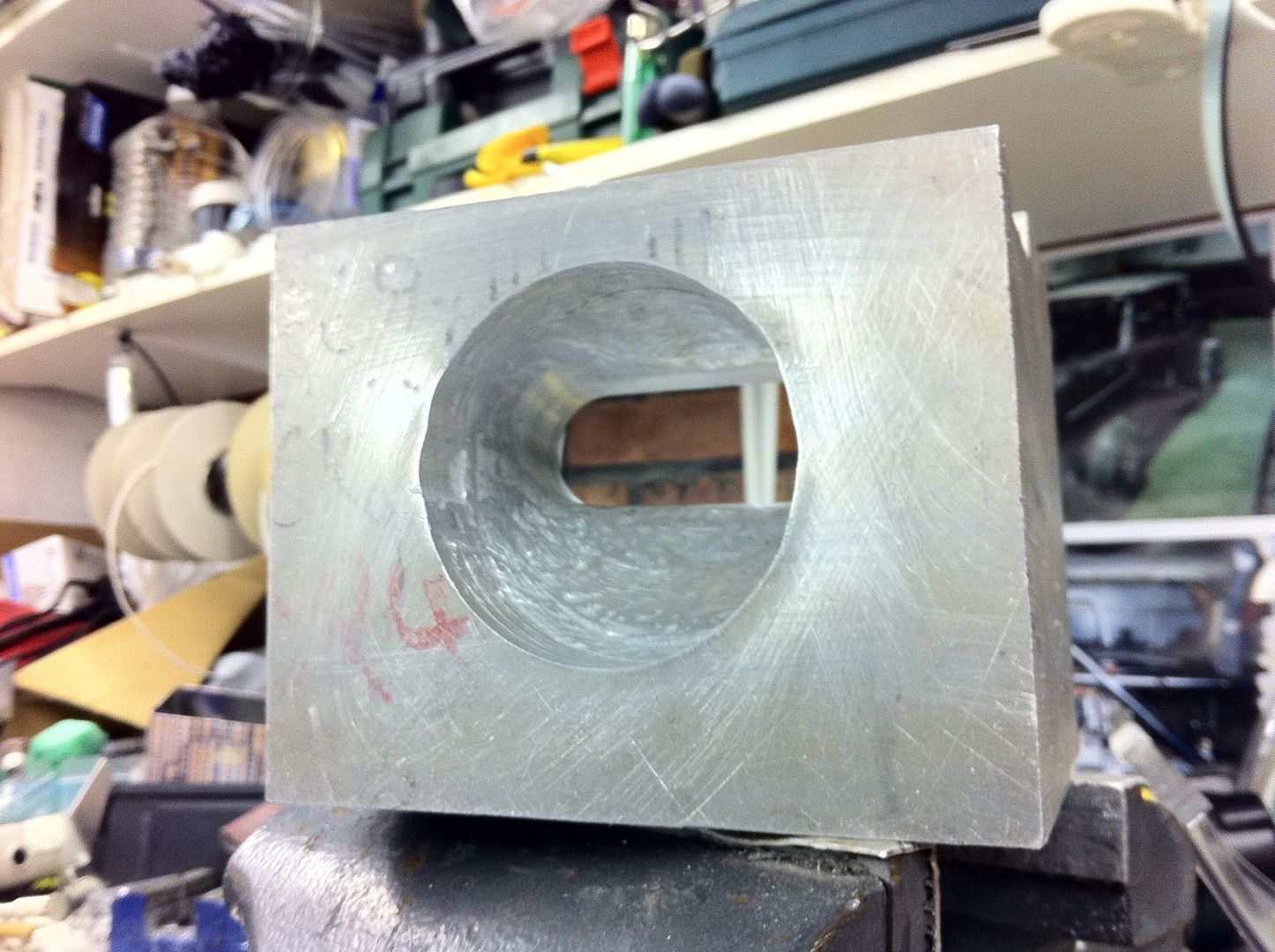
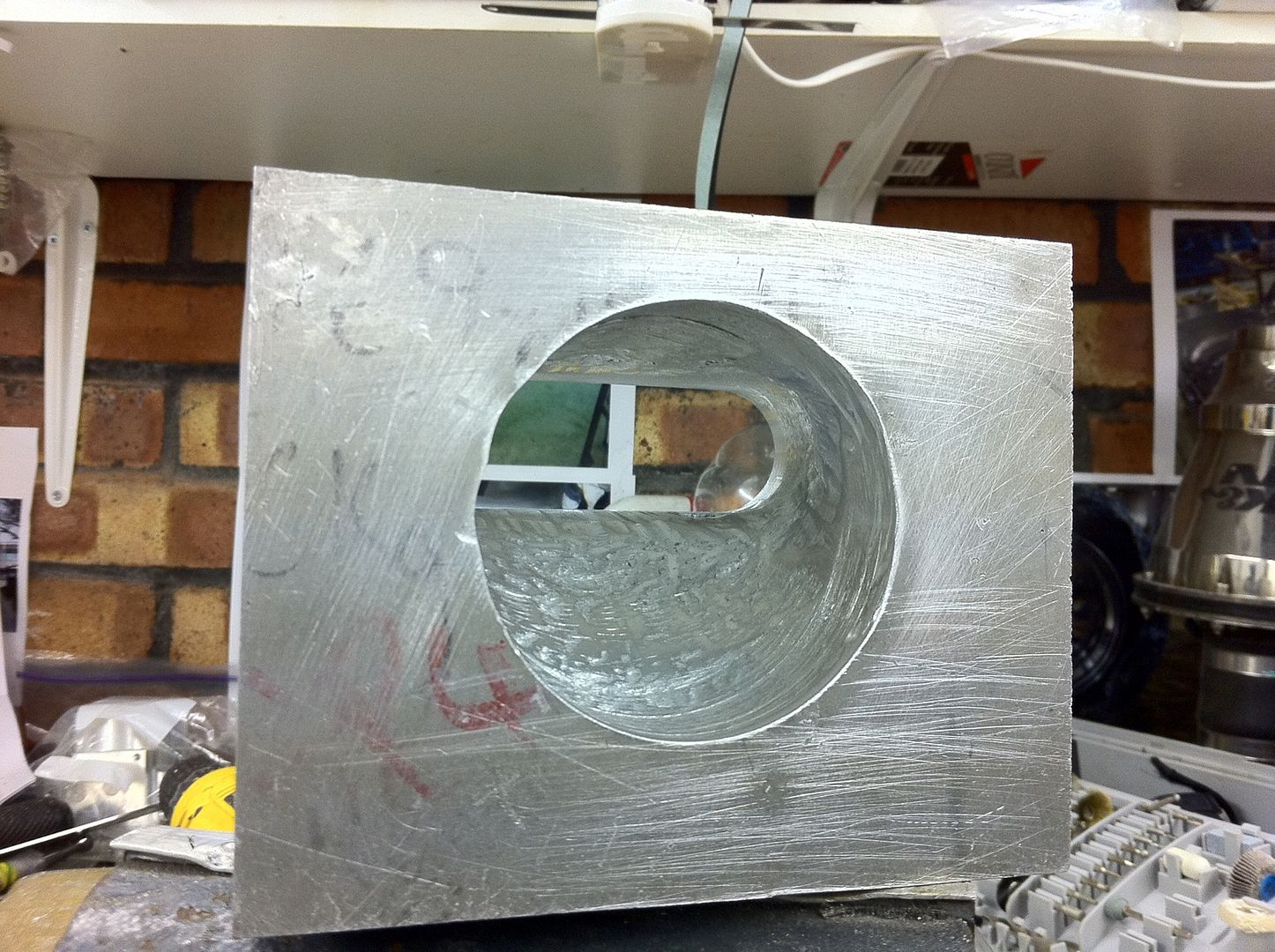
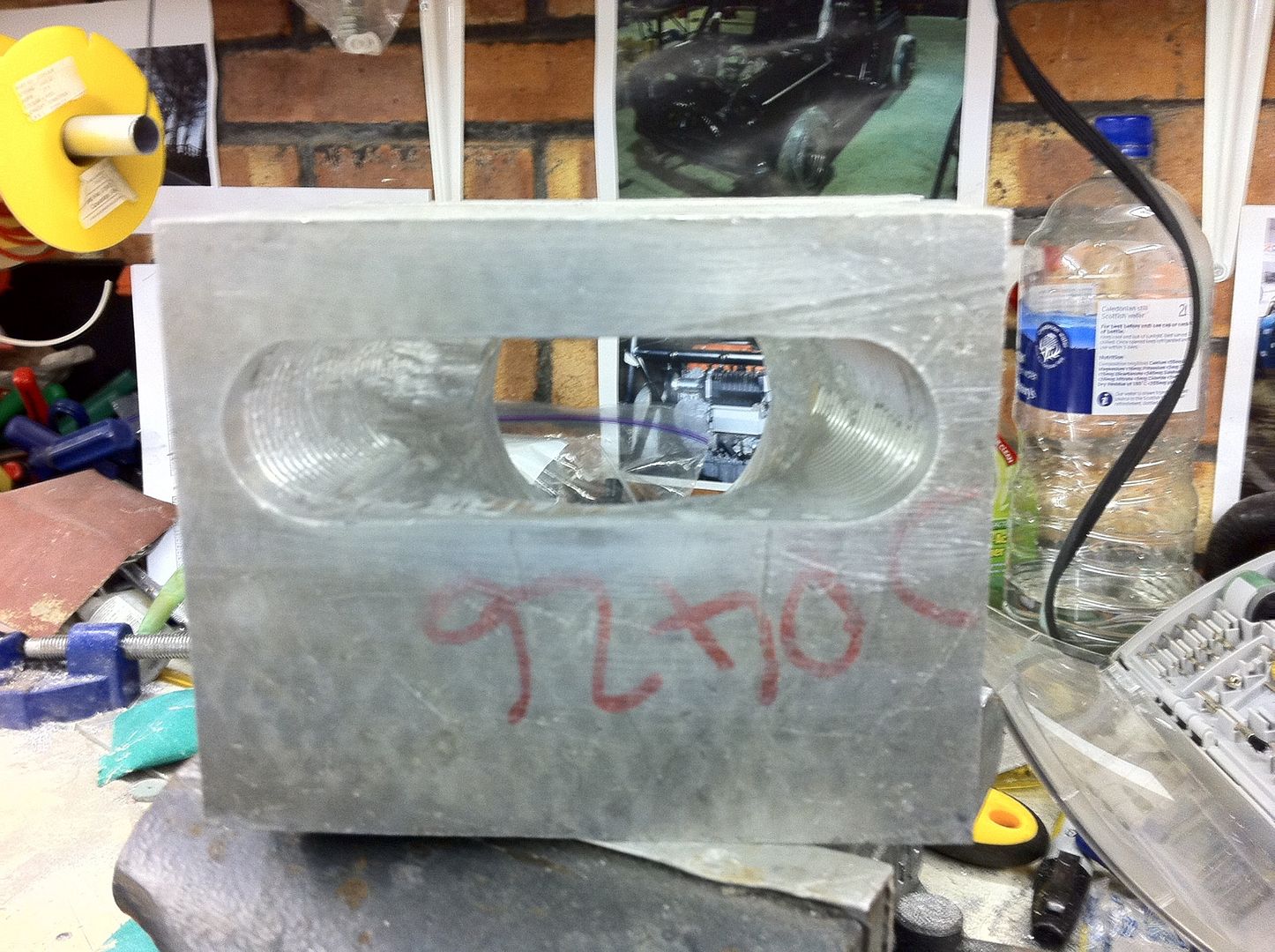
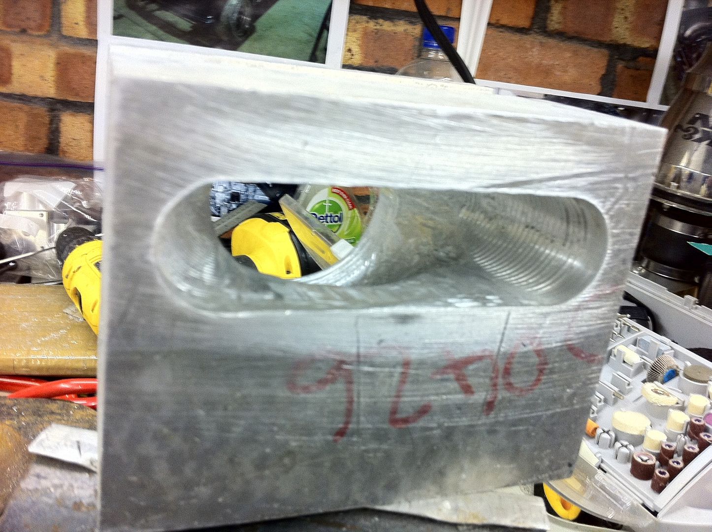
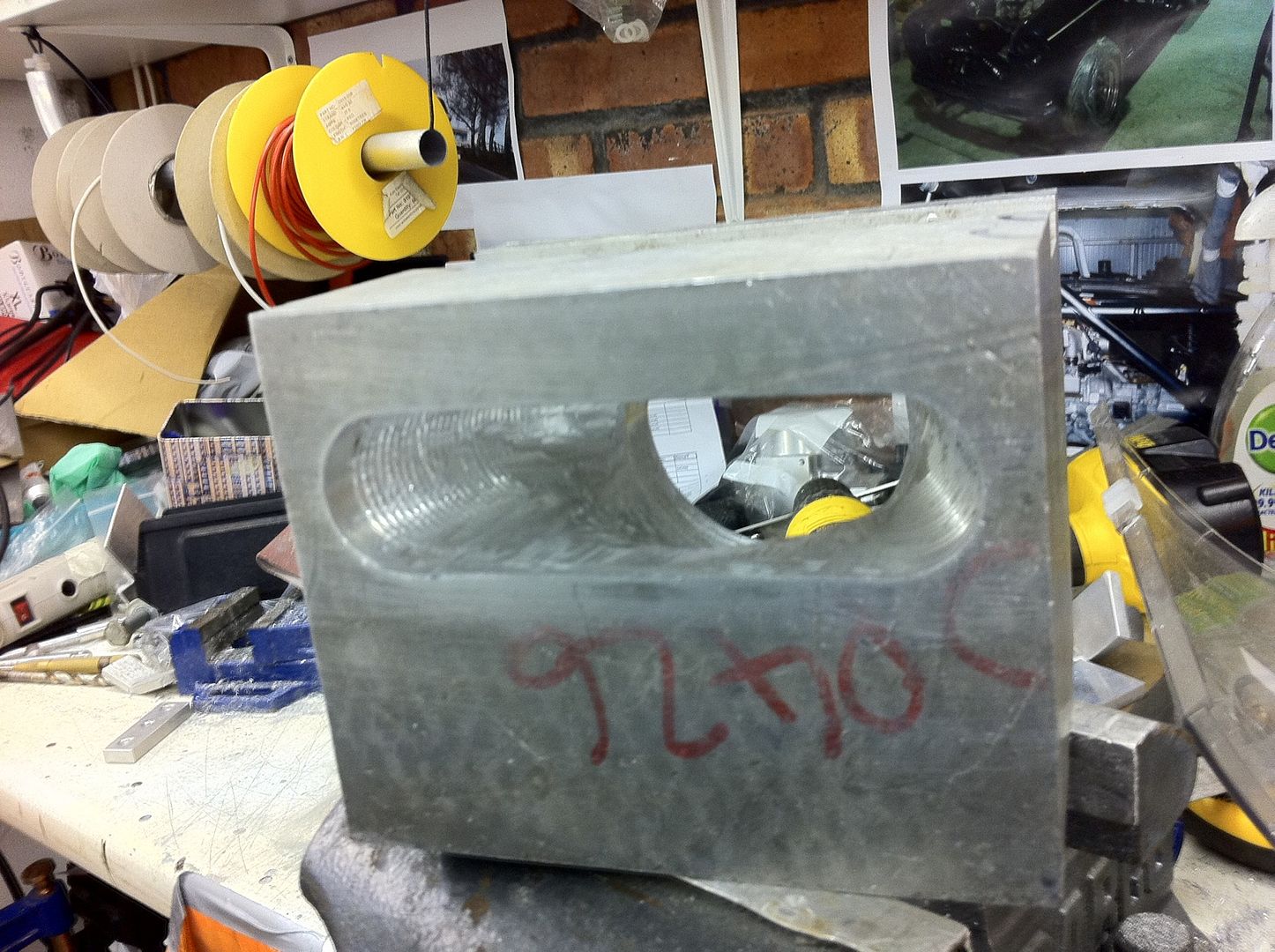
I spent 3.5hours with a die grinder trying to get the inner tunnel shape of the TB-SC Manifold done, I got the basic shape but the finish to the tunnel surface needs some work.
So it went from this:
To this:
Going to do some more sanding and smoothing to the tunnel, but at least we can now start on the outer machining which shouldnt take too long.
9 user(s) are reading this topic
0 members, 9 guests, 0 anonymous users