Supercharged K20a2 Vtec - Race Spec
#766

Posted 11 January 2012 - 01:37 PM
#767

Posted 18 January 2012 - 12:17 PM
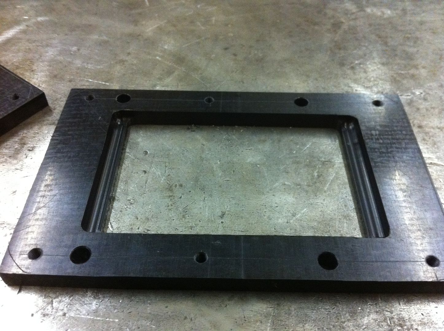
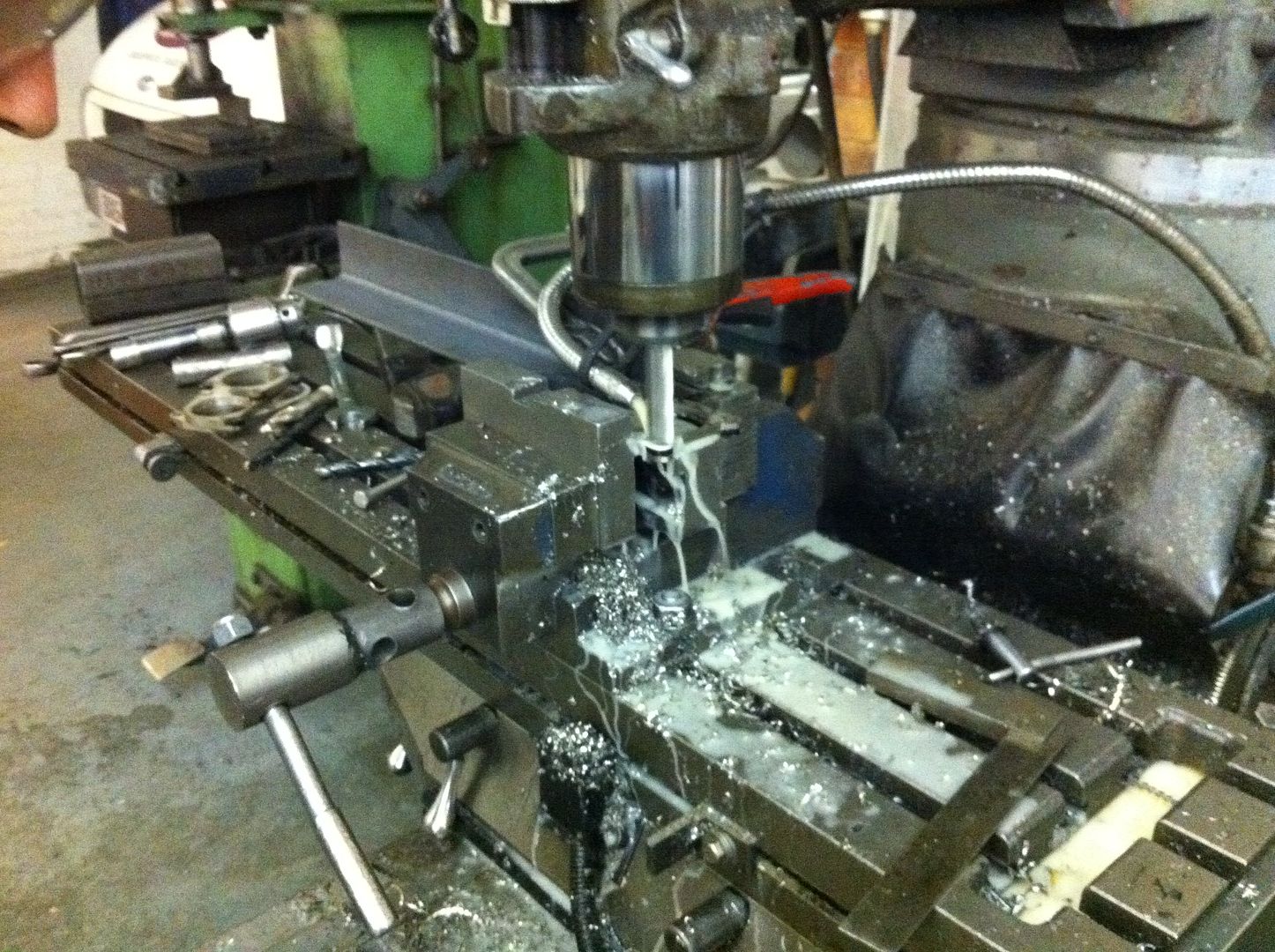
I finished my adaptor plates, instead of a flat angled side I used a ball nosed mill cutter. Thanks again to Stevie G for doing this for me.
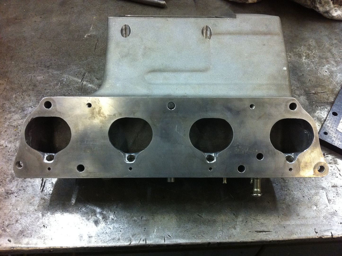
Whilst Steve was milling my adaptor plates I took the time to use his die grinder and open up the inlet ports on the intake manifold, you can see in the picture below the scribed lines taken from the OEM gasket, this shows how the casting isnt the best especially around the injectors so I opened it up and whilst in there I did a bit of flow work on the manifold as it had some 'interesting' angles before the openings.
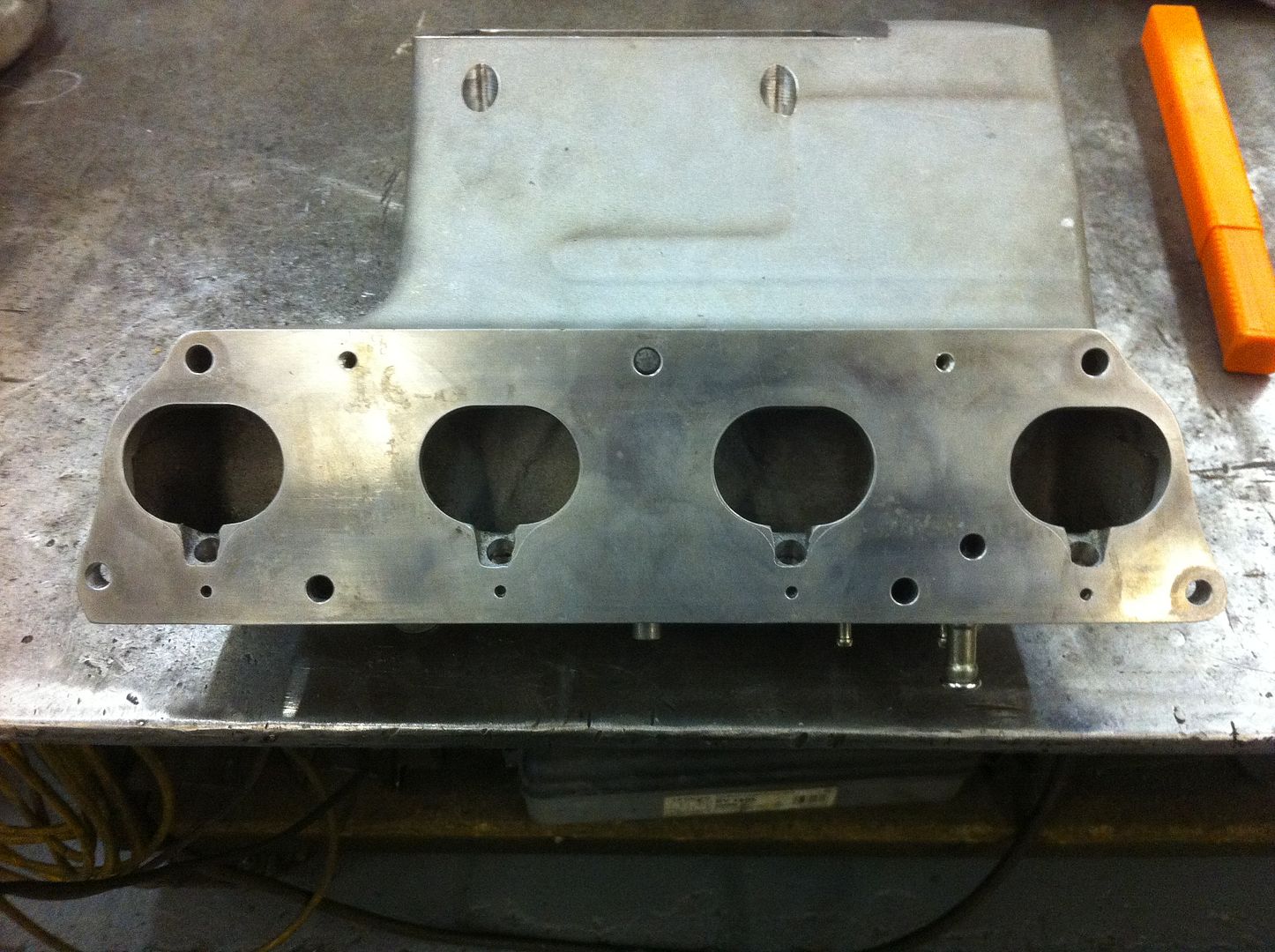
After:
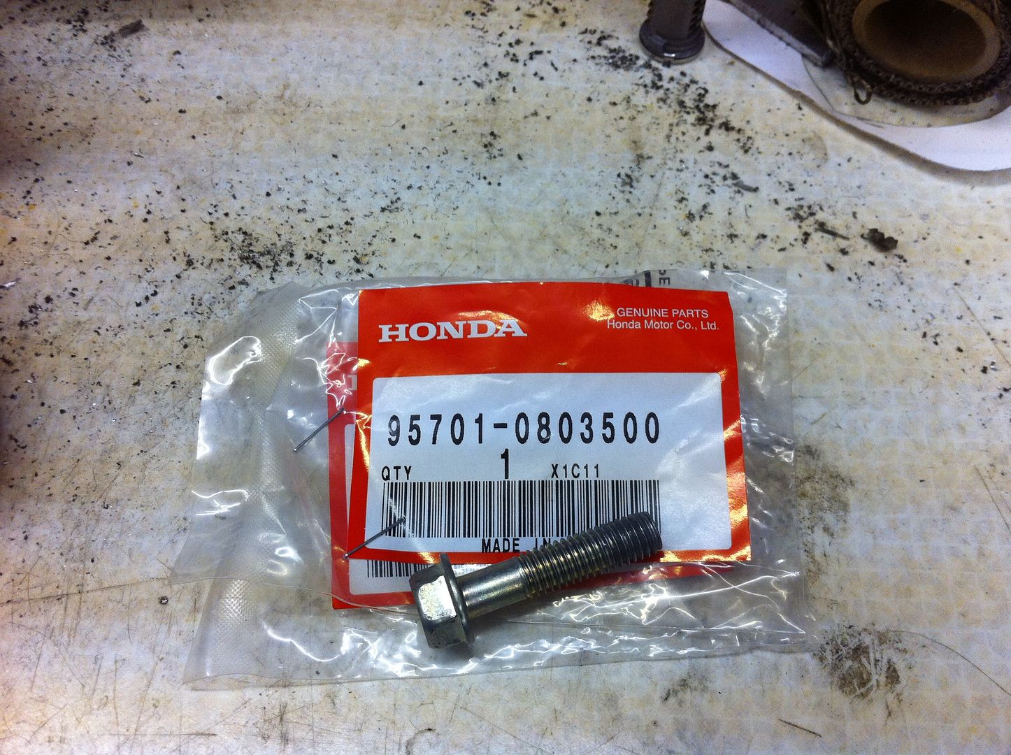
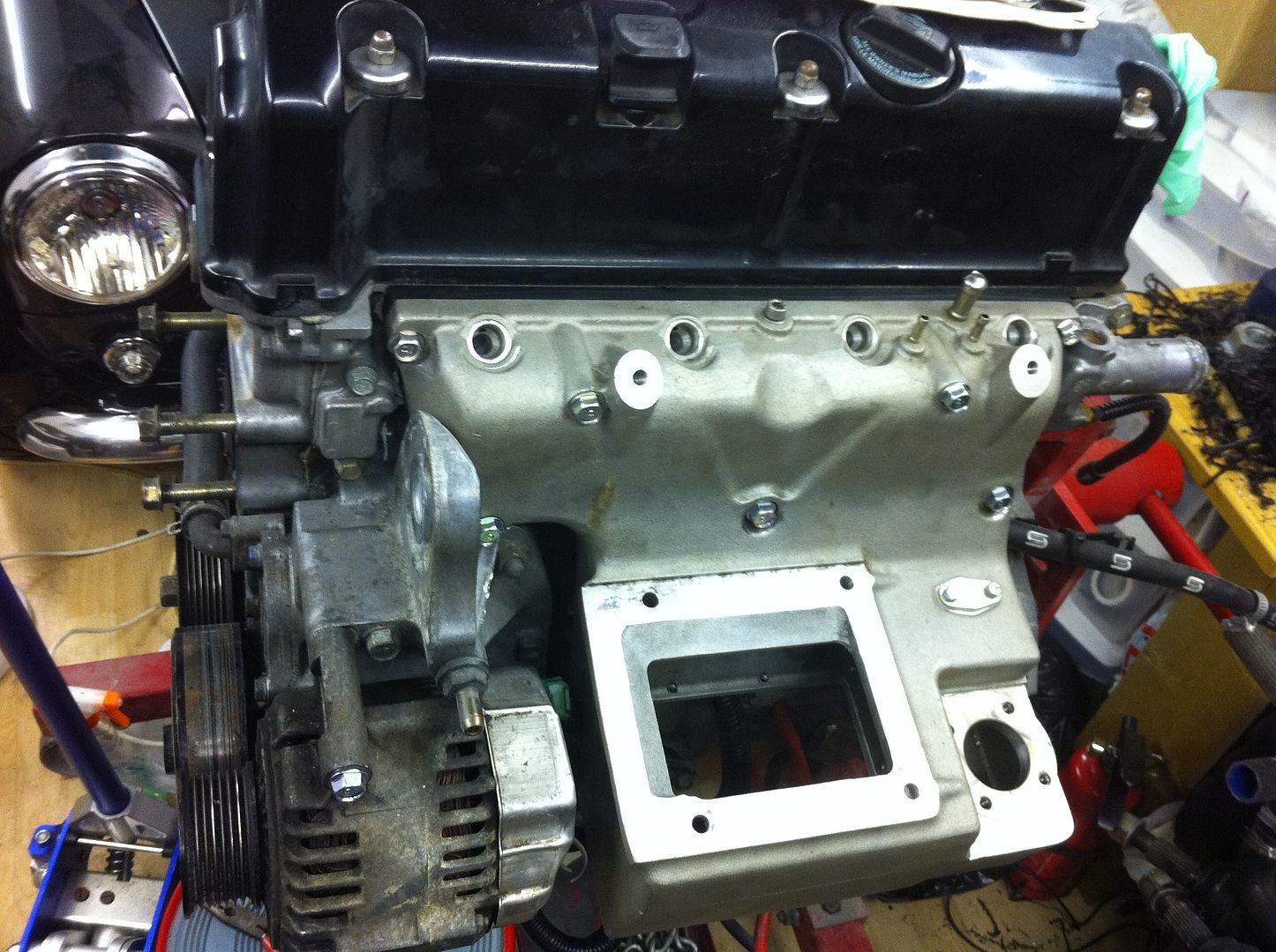
I managed to source a 35mm bolt in a zinc coating from Honda and put the intake manifold on to test fit it and make sure nothing was fouling.
Bolt:
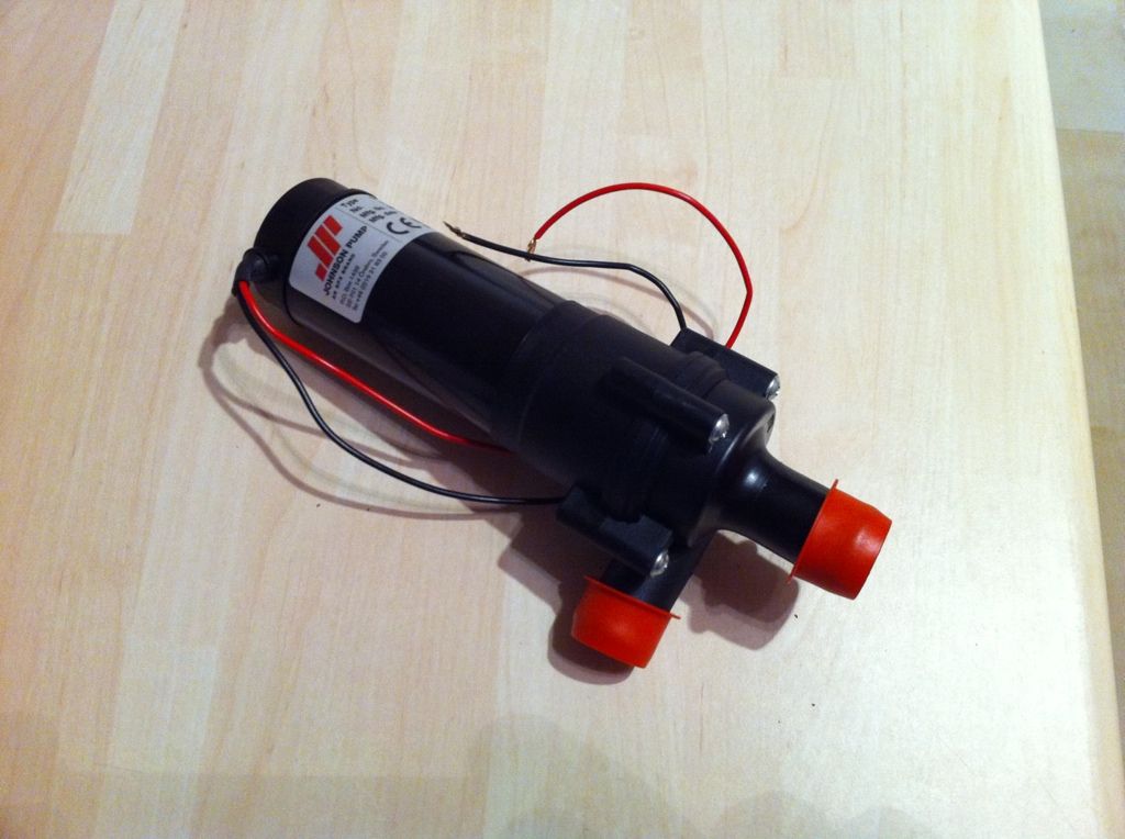
I also got my I/C water pump yesterday from the good ol US of A - its a Johnson CM30 pump, reputedly one of the better 19mm pumps on the market and very compact, even compared to the bosch unit:
#768

Posted 18 January 2012 - 06:33 PM
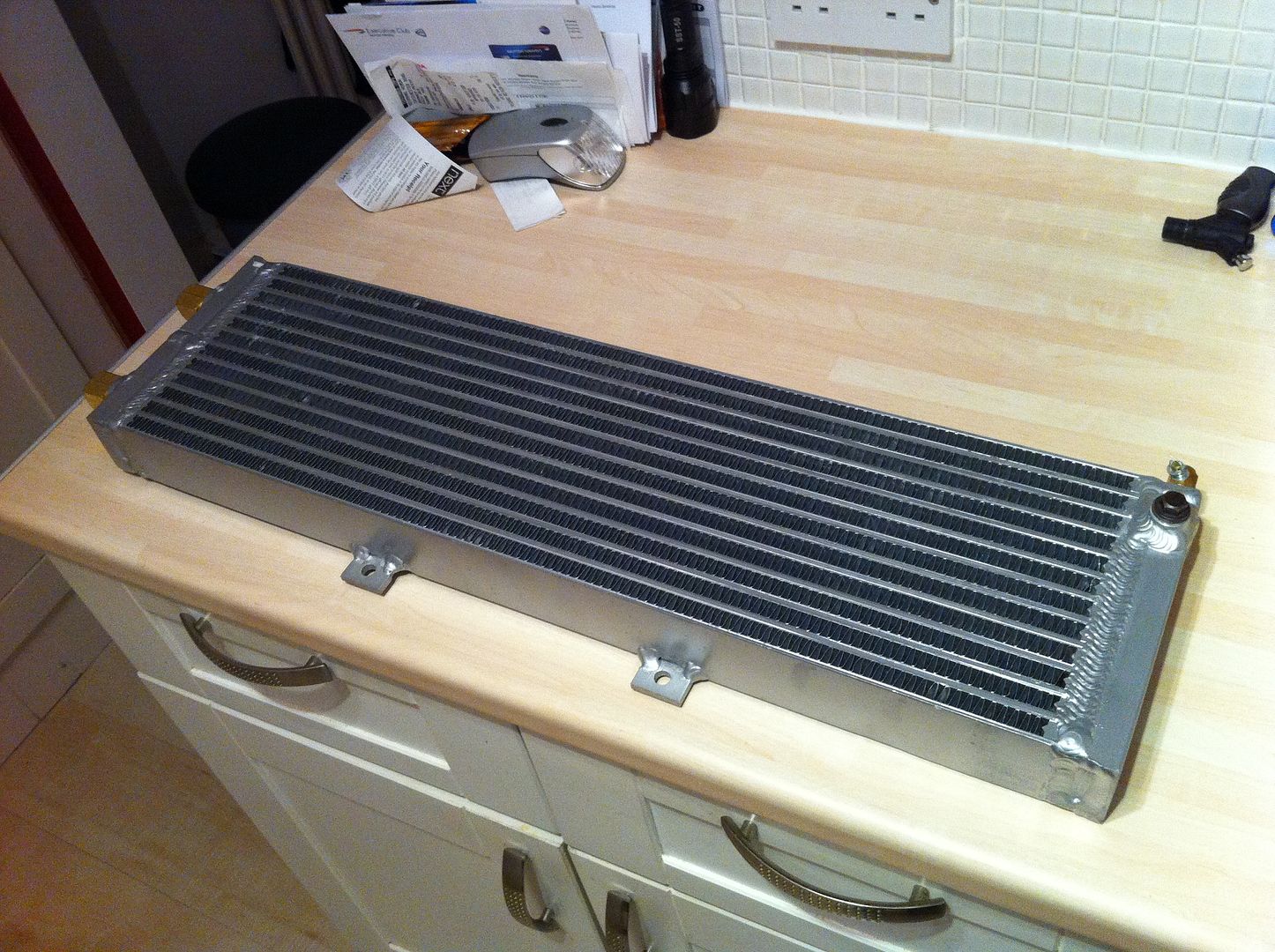
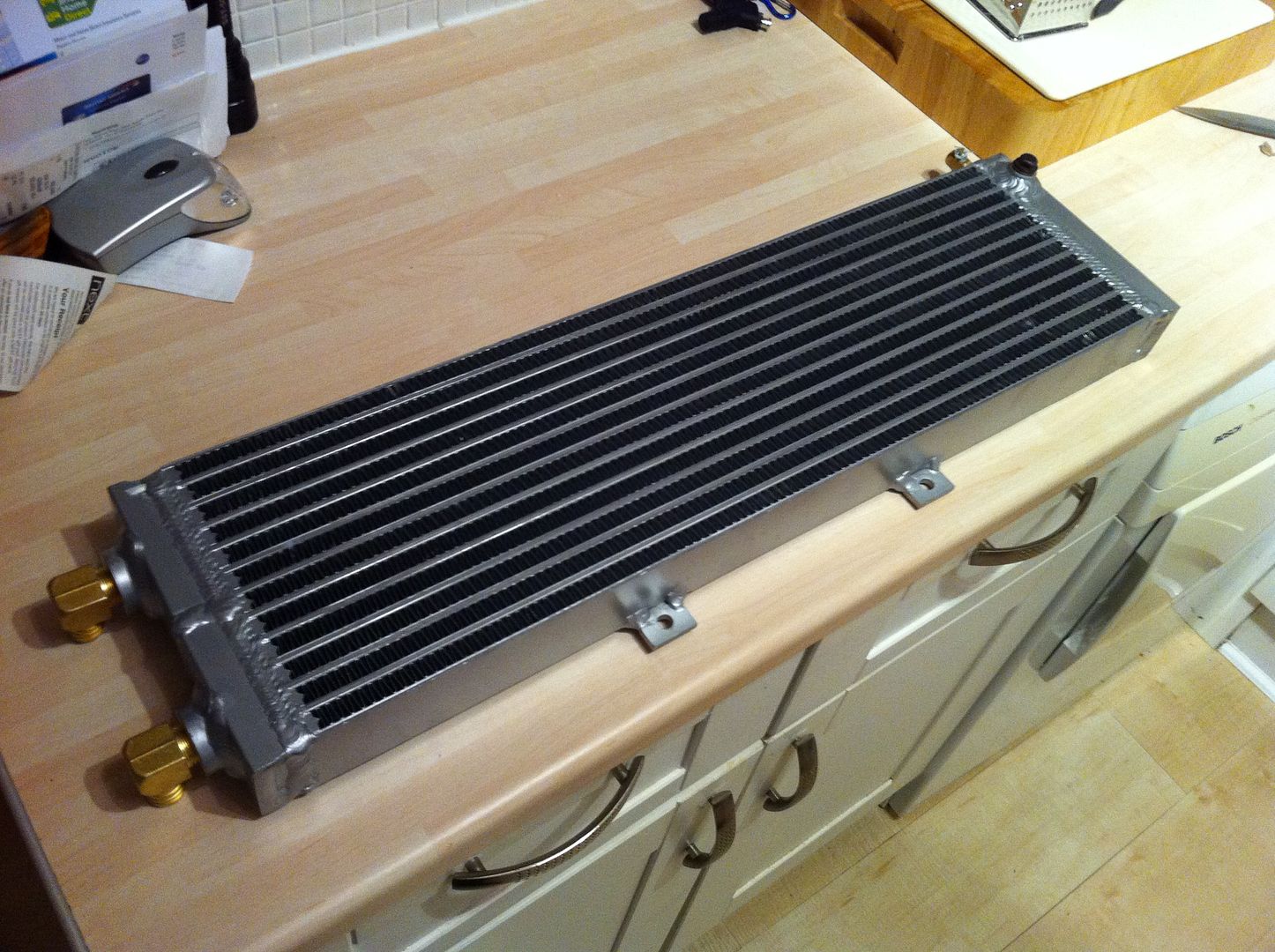
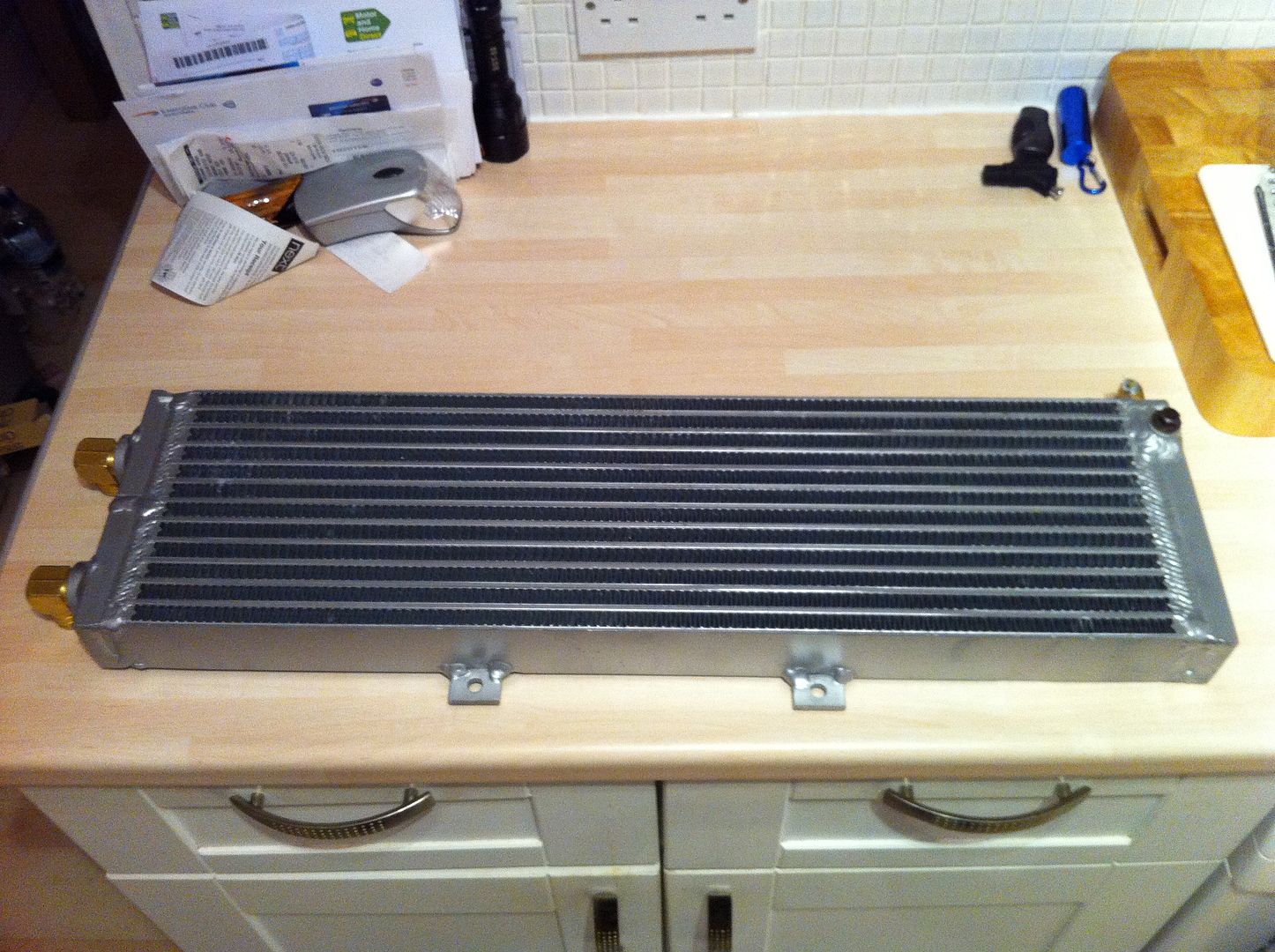
I got my radiator through today, I ordered it from FrozenBoost in the states as it worked out cheaper including taxes than buying in the UK. Now I have to work out how to squeeze it in behind the grille without too much messing around, time will tell.......
Intercooler Radiator:
#769

Posted 01 February 2012 - 08:24 PM
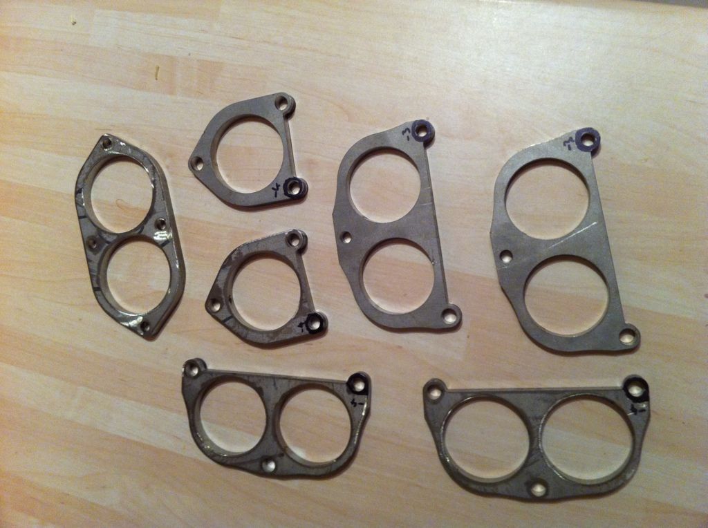
Yes I got my flanges through, I now need to machine the tabs and then get them welded into place - simples......
#770

Posted 01 February 2012 - 09:40 PM
#771

Posted 01 February 2012 - 10:15 PM
Only just noticed the post with the rad, I'm off on holiday on Friday so won't have time, but when I return (just over 2 weeks) I can take some pictures of what I've modified on mine to fit the radiator if it'll help? And if you havent progressed past that? The rad looks very similar in size too.
I think I know what I am going to do but any suggestions are welcome, thanks.
#772

Posted 16 February 2012 - 08:22 AM
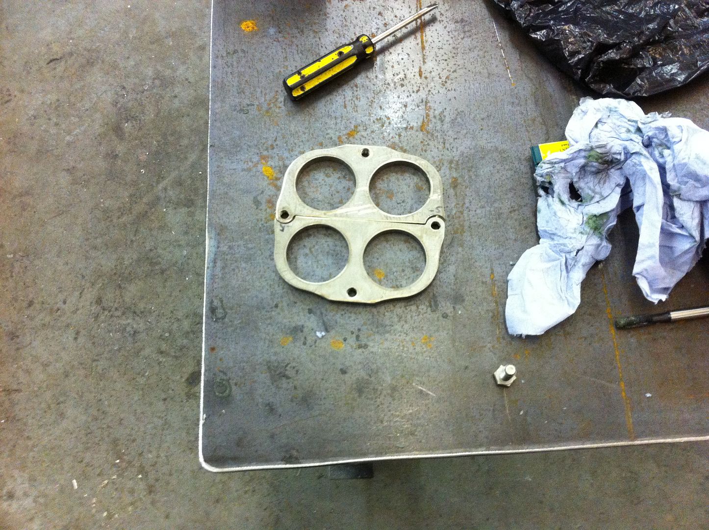
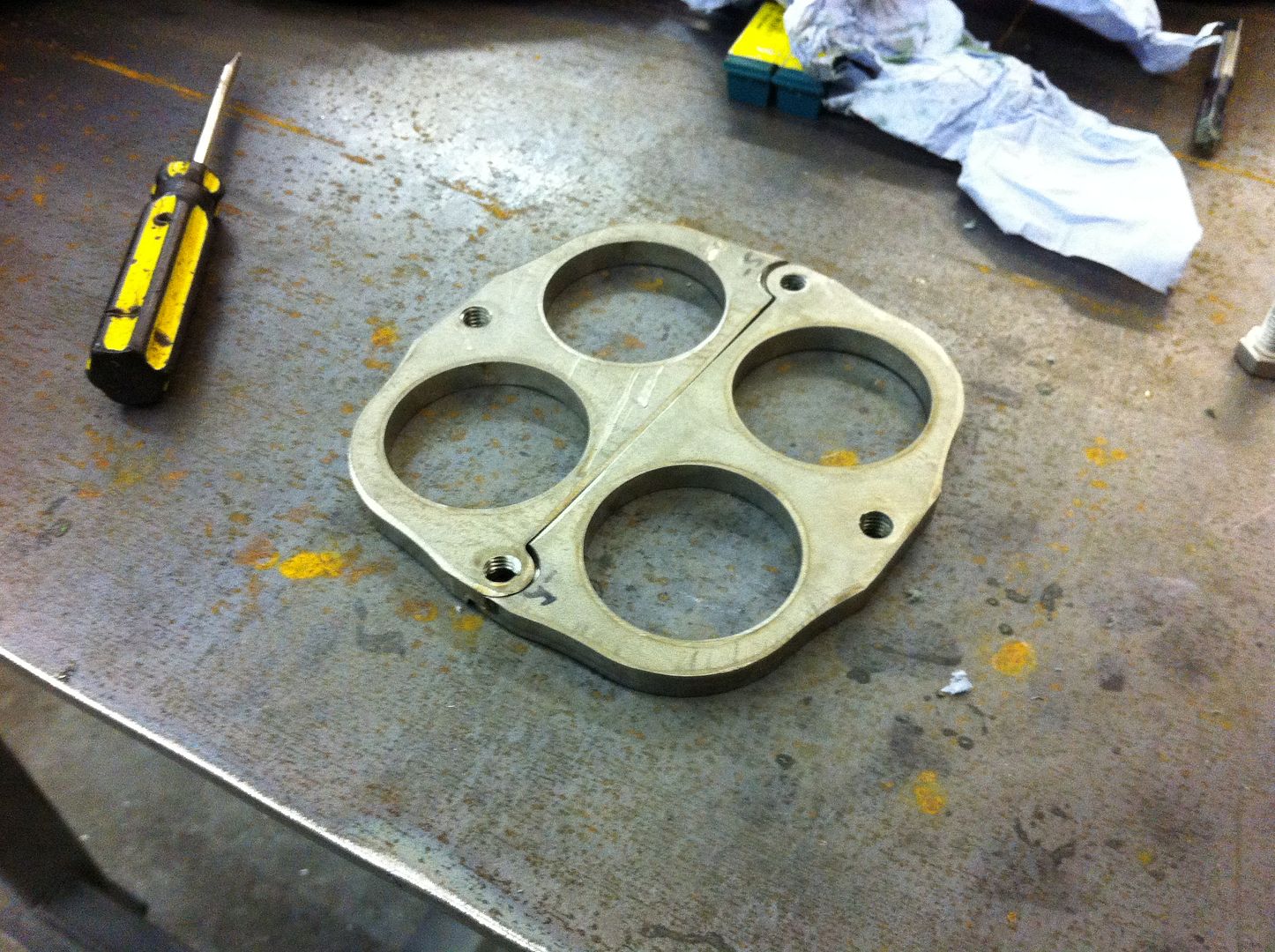
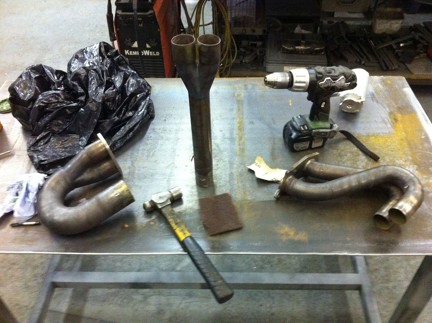
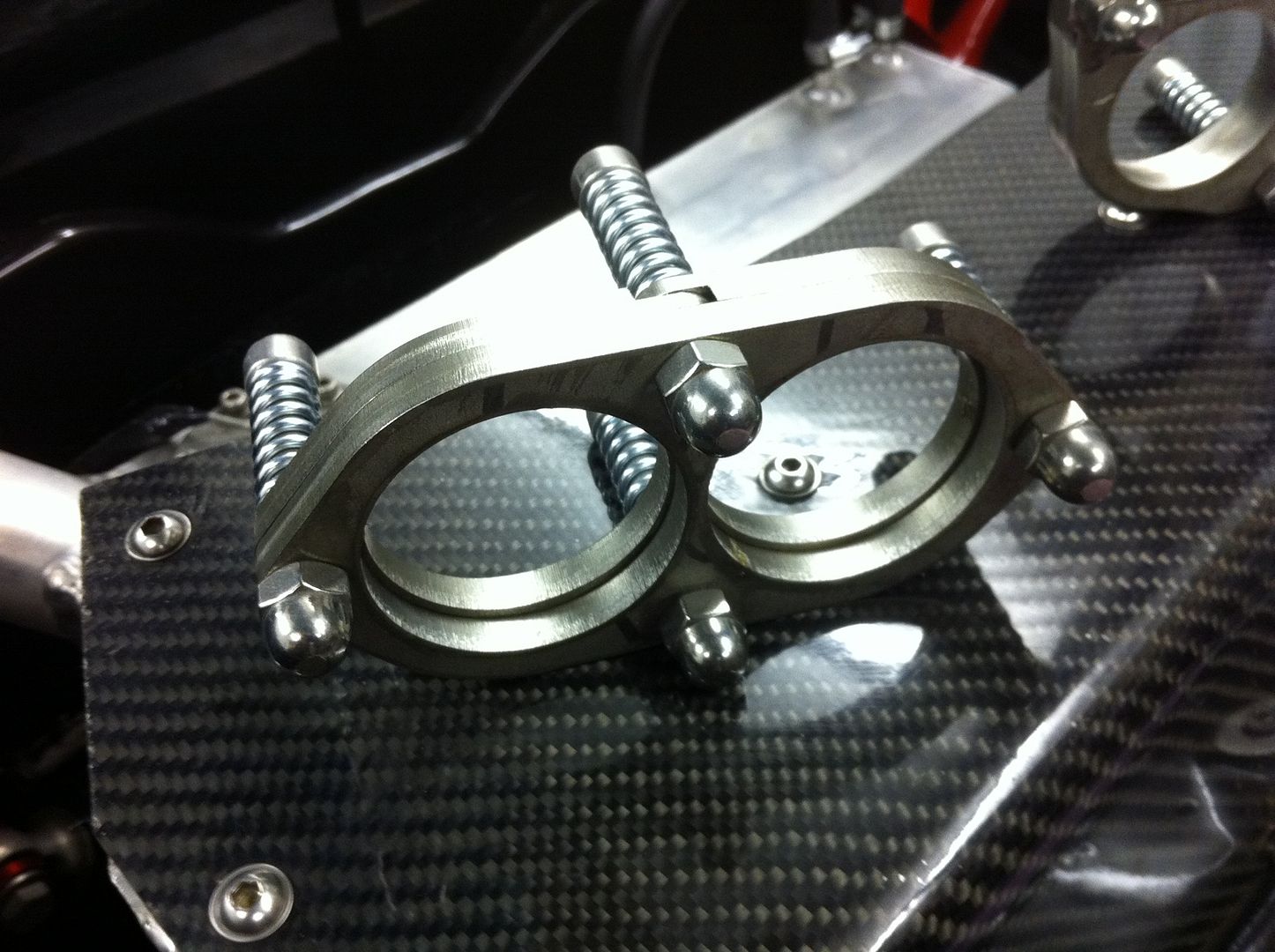
I got some more work done to my exhaust system last night, flanges are machined now so that they overlap (thanks Steve) and I threaded the holes that required threading. Even though they now overlap there appears to have been an amount of distortion during the laser cutting process so what looks like a nice straight edge where the two flanges meet it is infact a nice curved edge so I need to make that flat now. One of the flanges fits like an absolute dream as you can see in the photos there is one flange sat on the pipe where it goes from 2 to 1 and then round 180degs. Fingers crossed this should I should have done enough fettling by the end of the weekend to get this little lot welded up to a point then I need engine back in before I can weld the last two pieces in place.
I made a list of stuff to do before April and I have come to the decision that I really need to extract the digit if I am going to get it remapped and ready for RAF Marham late April........
Pictures of flanges - heh heh heh.......I know its childish but hey........
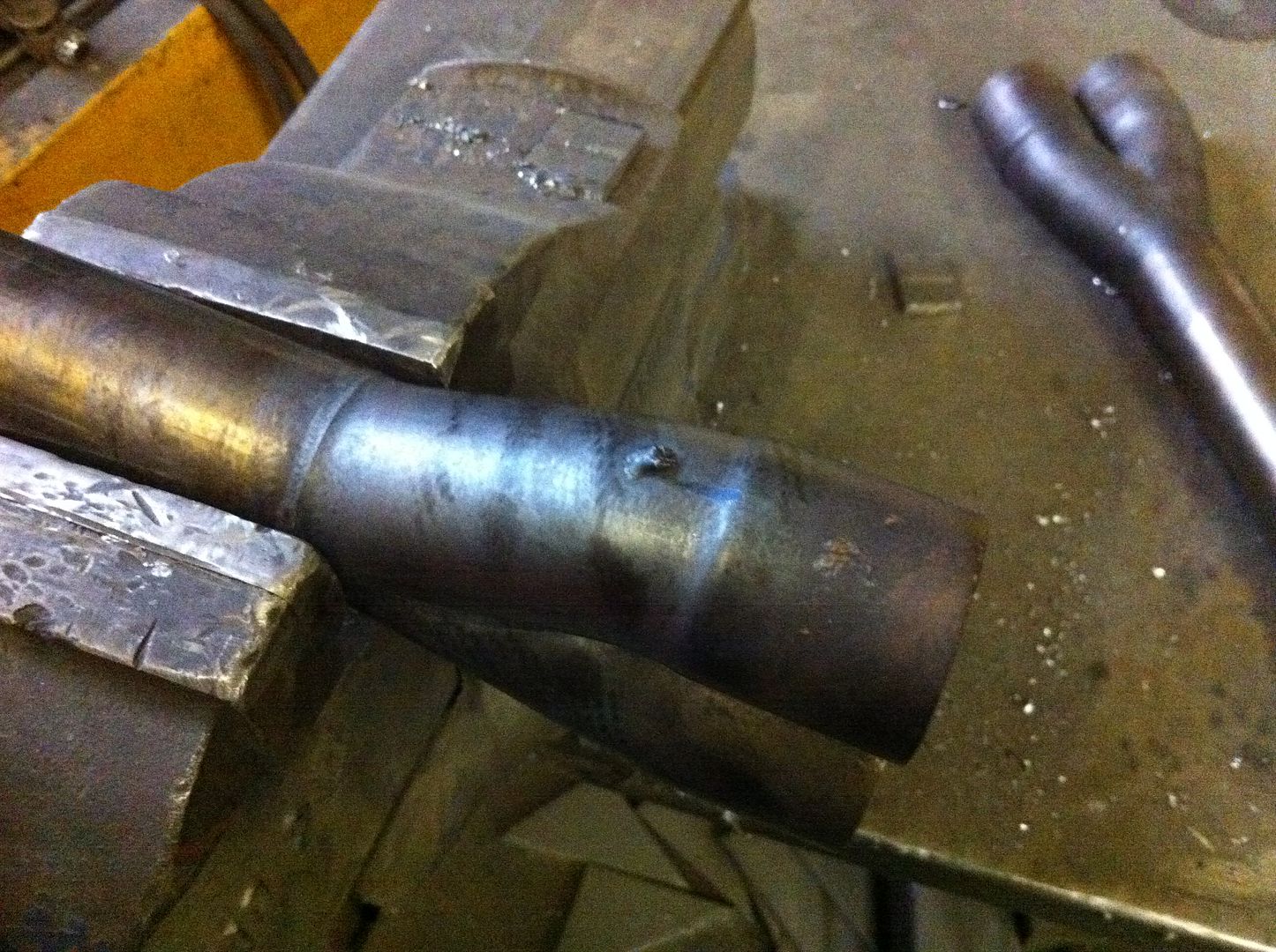
These are of me removing the old spring connections - basically a loop of welding wire that you hook the spring to to hold the exhaust system together - great if you're racing as it saves weight and you can pull the system apart really easily, however in a road car not great as they leak fumes into the engine bay/cabin and the loops of wire snap off, in turn your springs drop off and let even more fumes into the cabin.....moan over.....
A snapped loop:
A recently removed loop and some old loops:
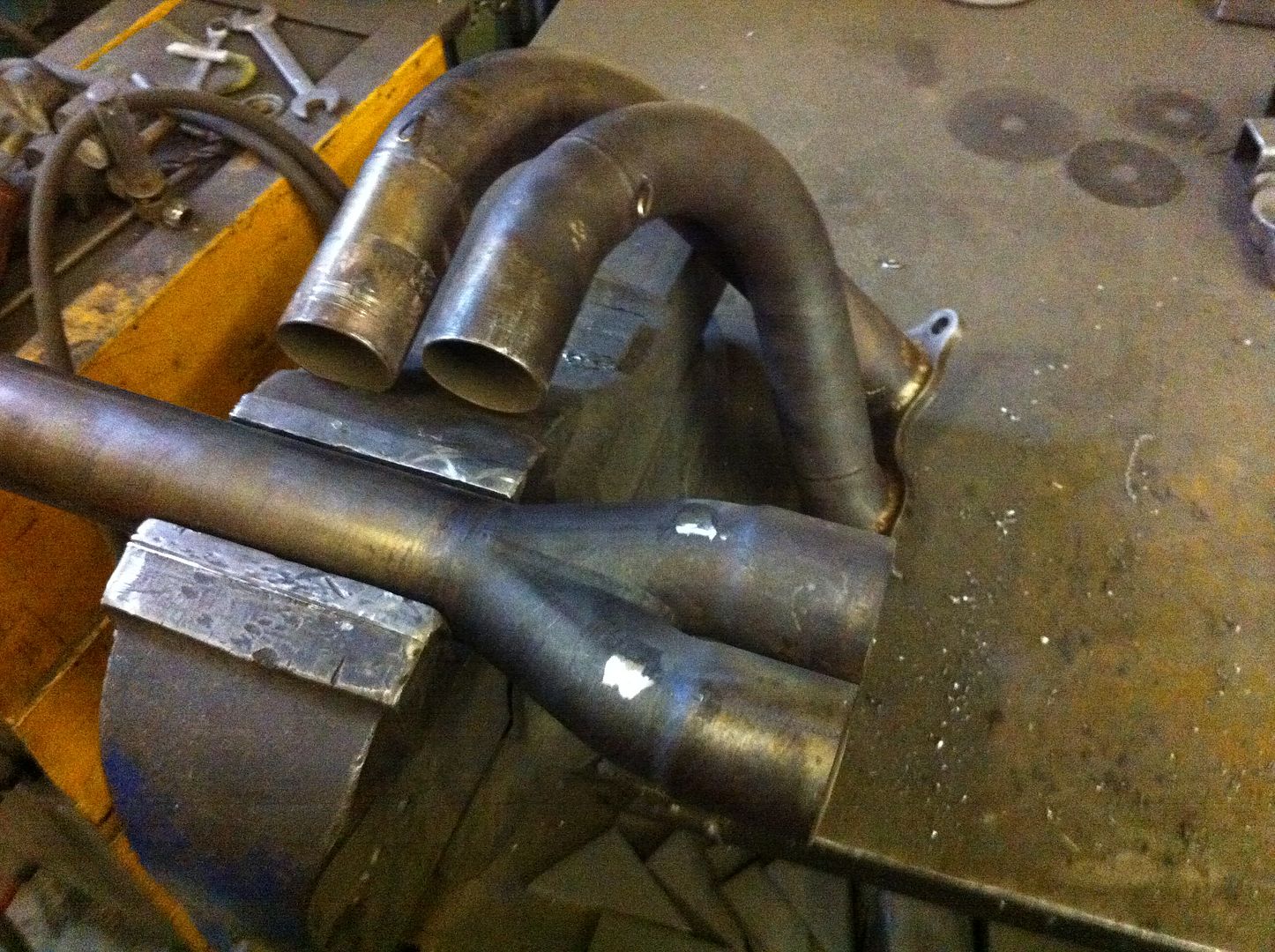
General photo - you can see the good flange in this one:
#773

Posted 19 February 2012 - 09:48 AM
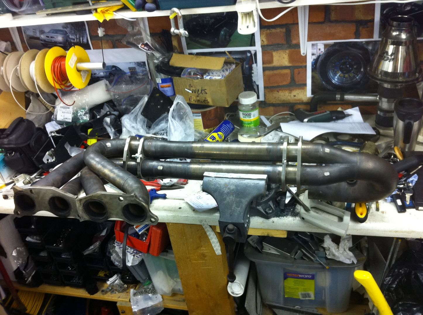
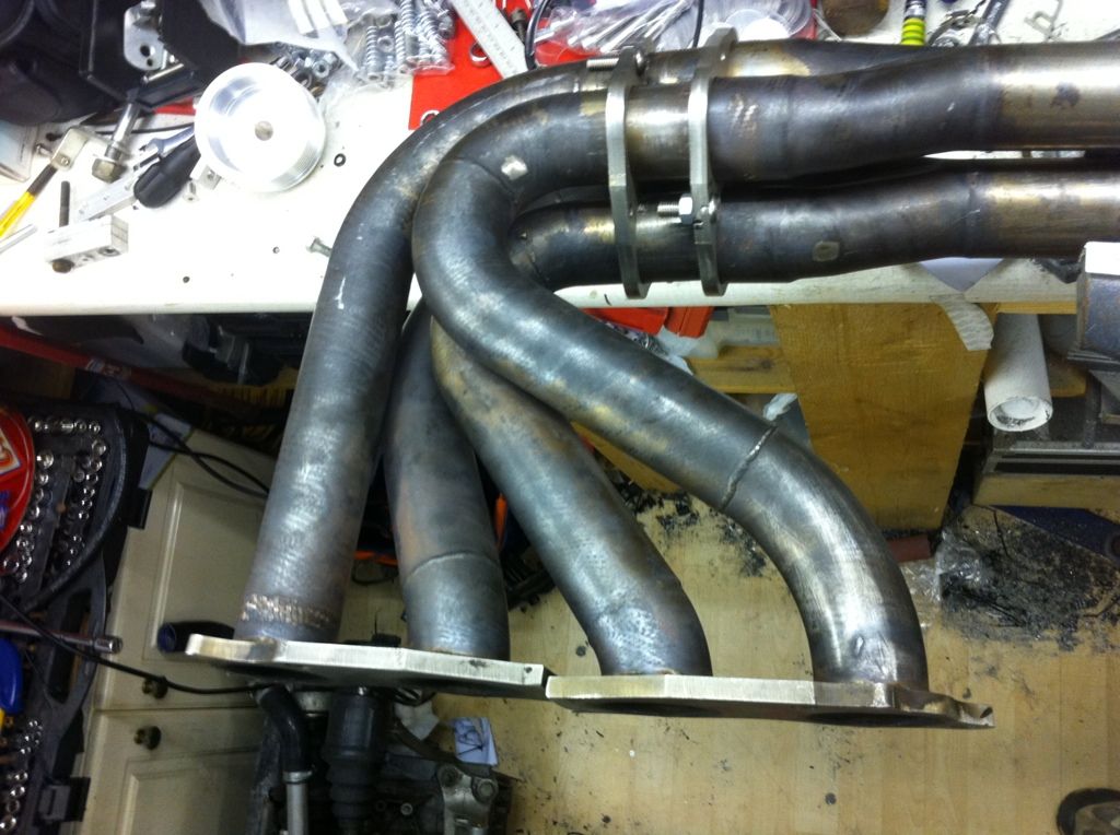
After an amount of fettling I managed to get all the flanges to sit sweet with each other and offered them to their relative flanges and test bolted them together as you can see in the photos below. I then fitted the flanges onto the pipes with a little persuasion. One thing that has come to light is that I will need to make a slight alteration to one half of the headers (header comes in two pieces, two pipes on each), you can also see this on the photos below.
I am going to be working on the car today so hope to have more progress to show......
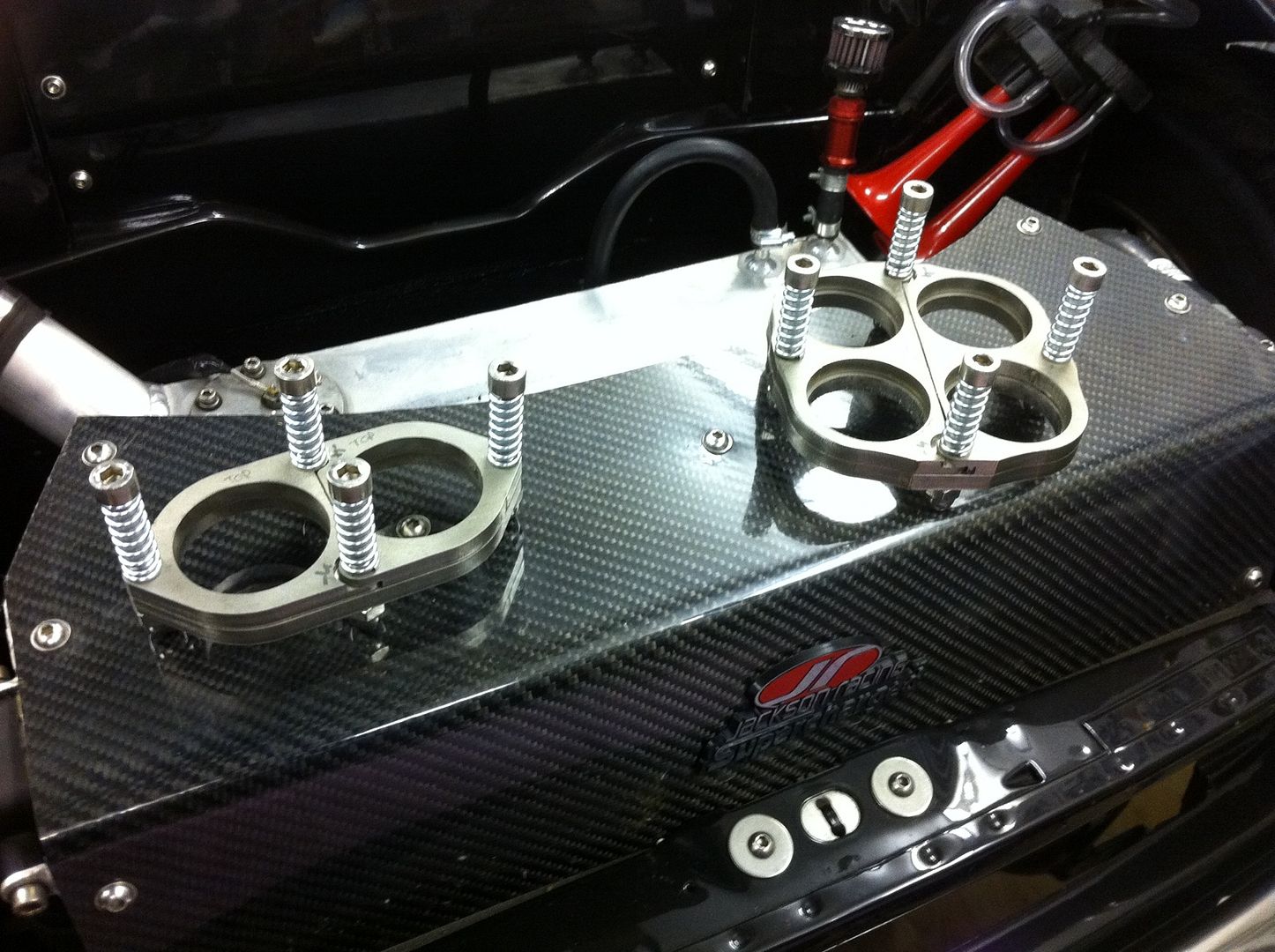
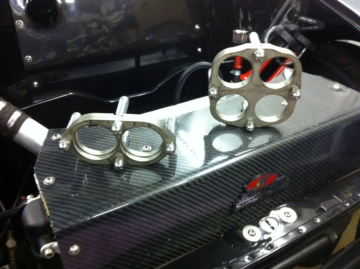
Offering the pipes to each other to get a feel if everything was ok:
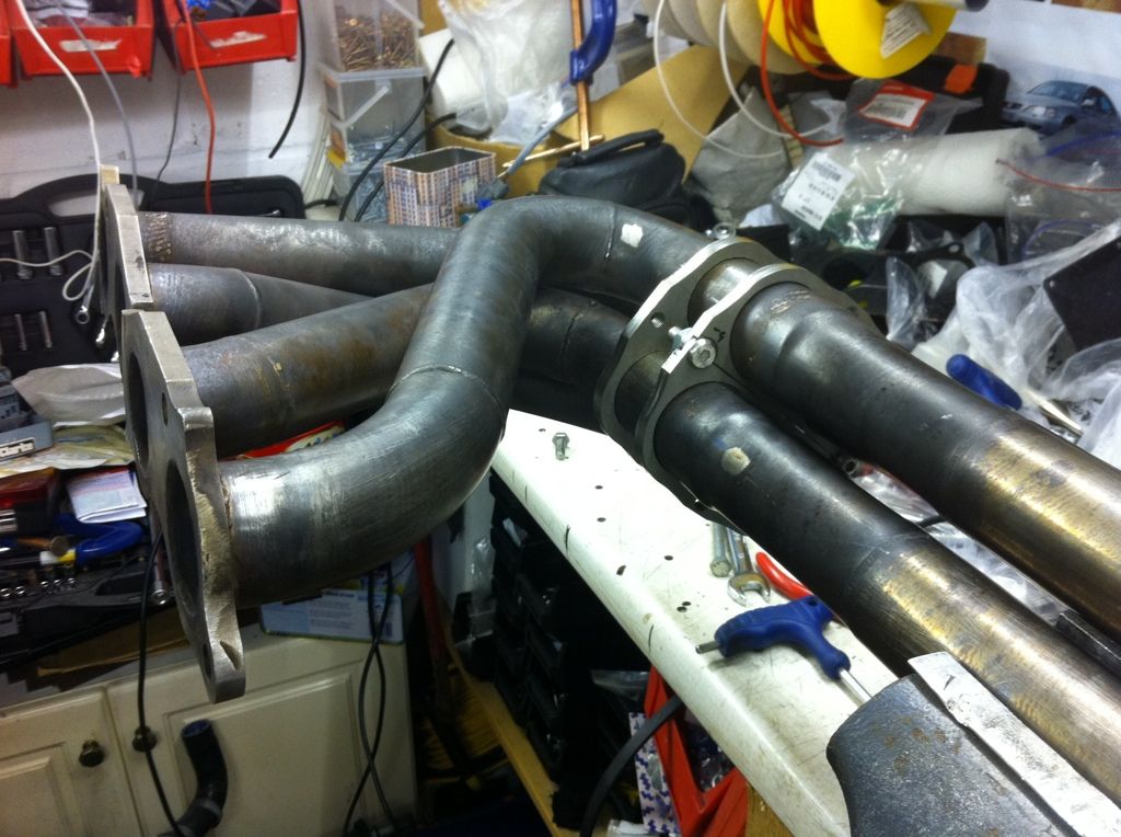
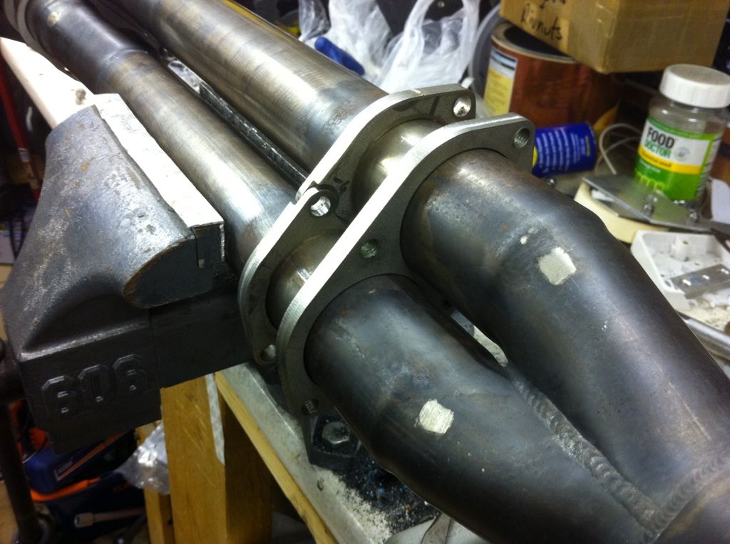
Finally the new misalignment of the header manifold:
#774

Posted 19 February 2012 - 02:08 PM
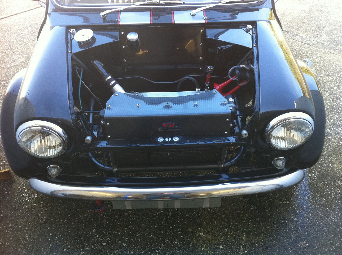
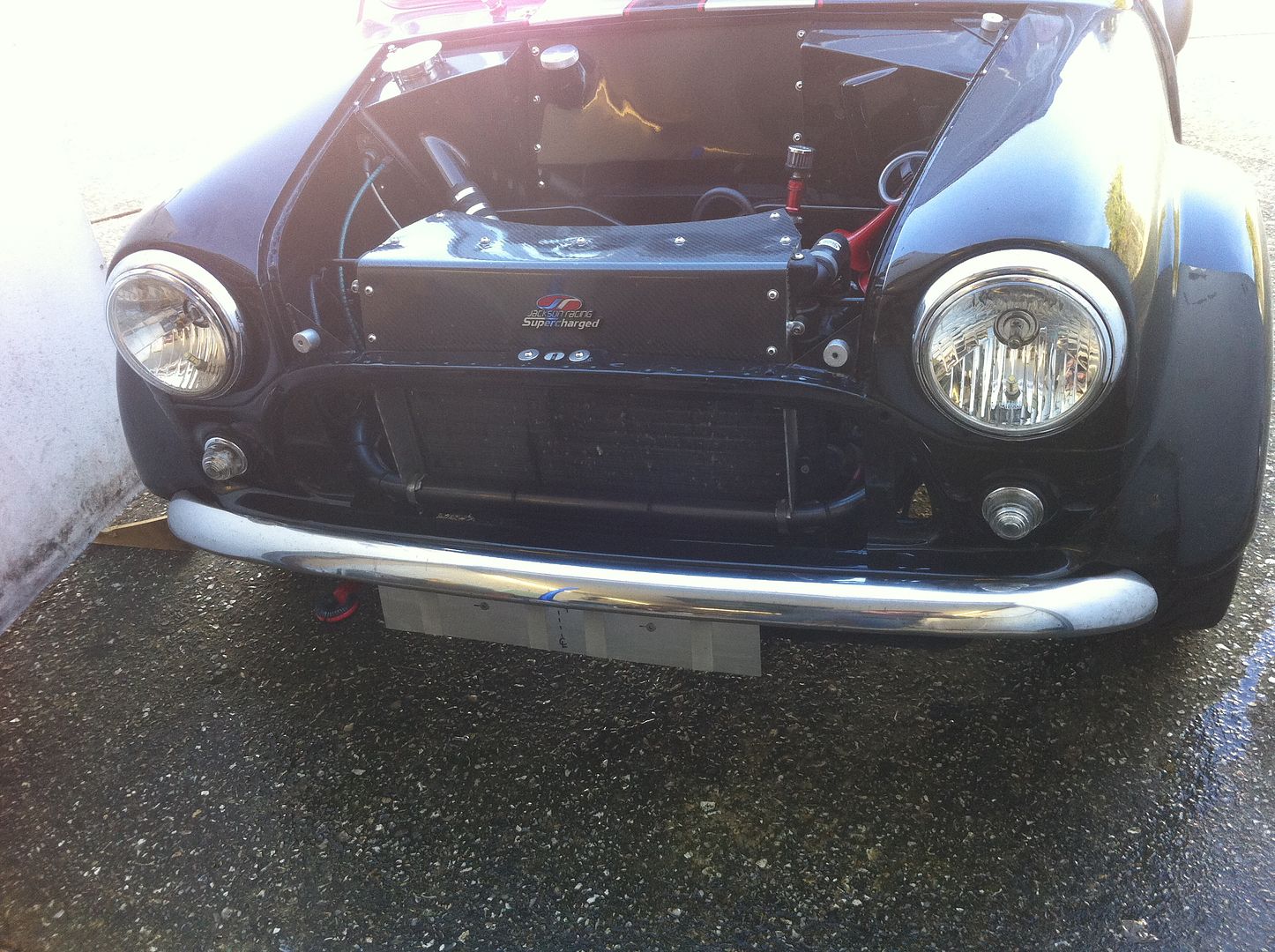
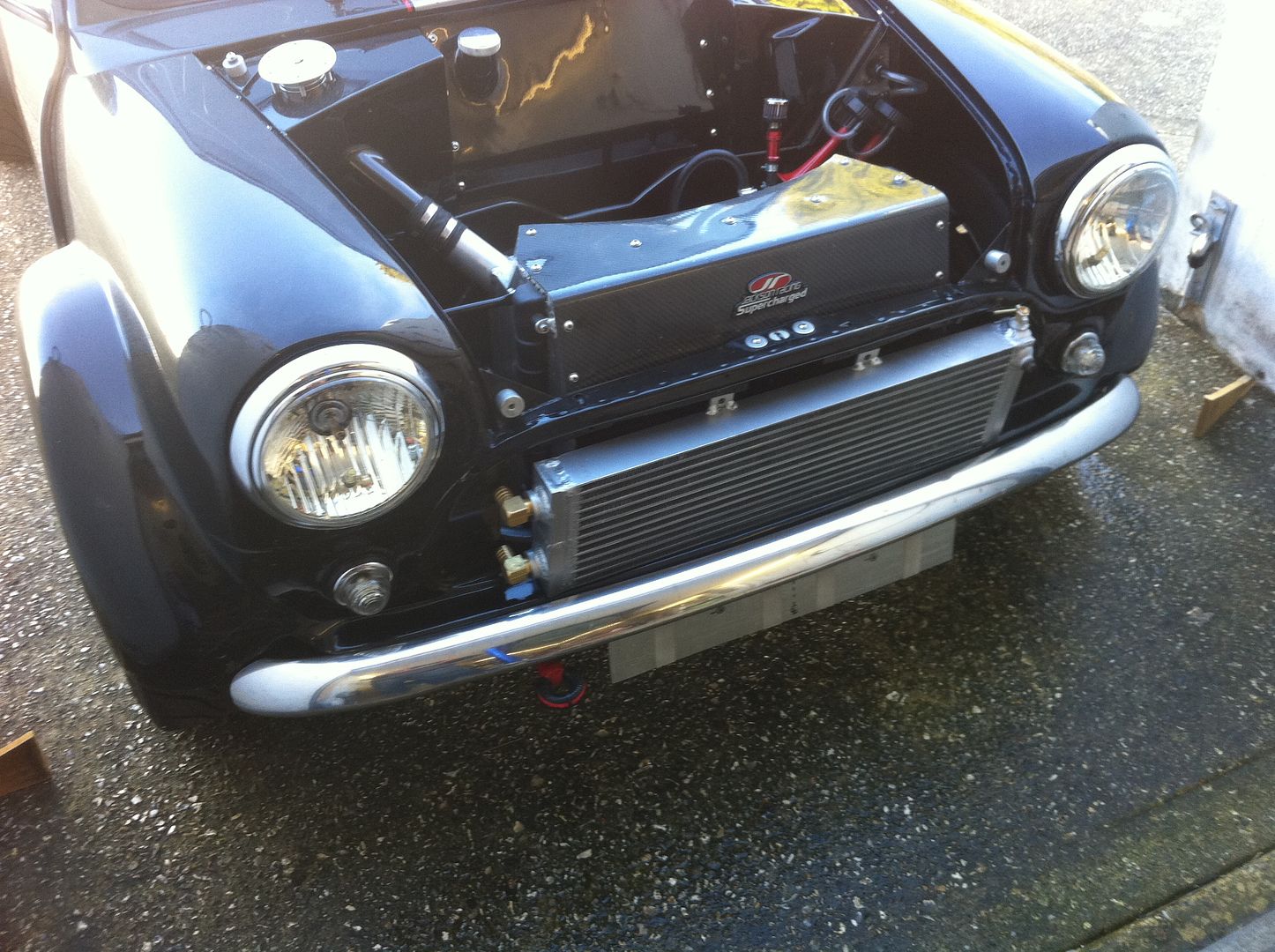
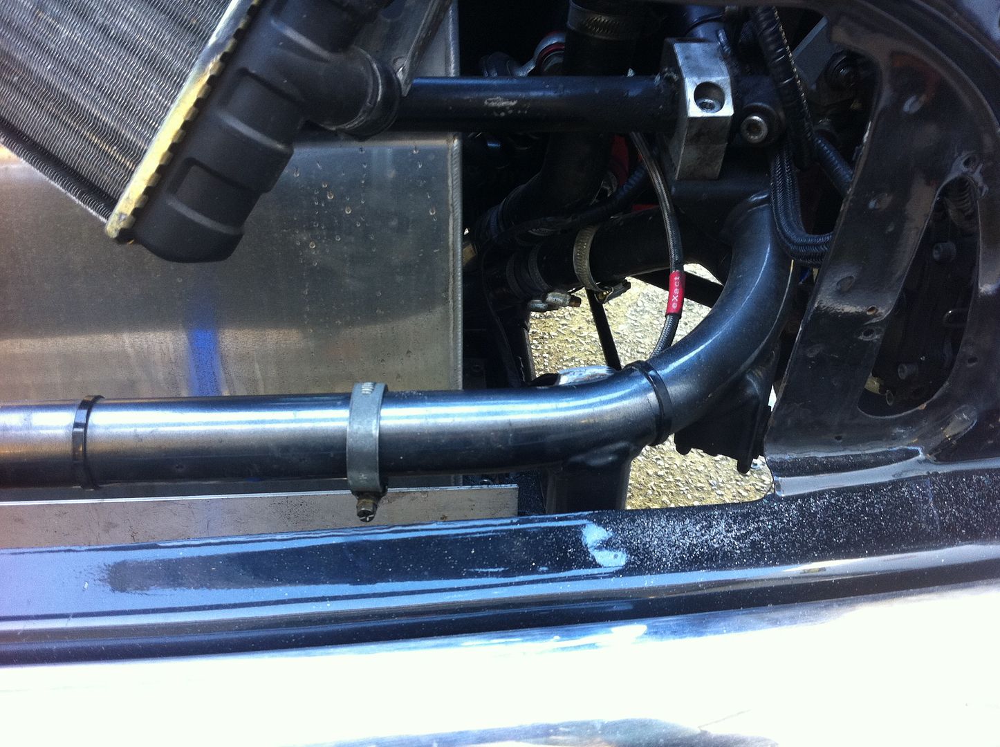
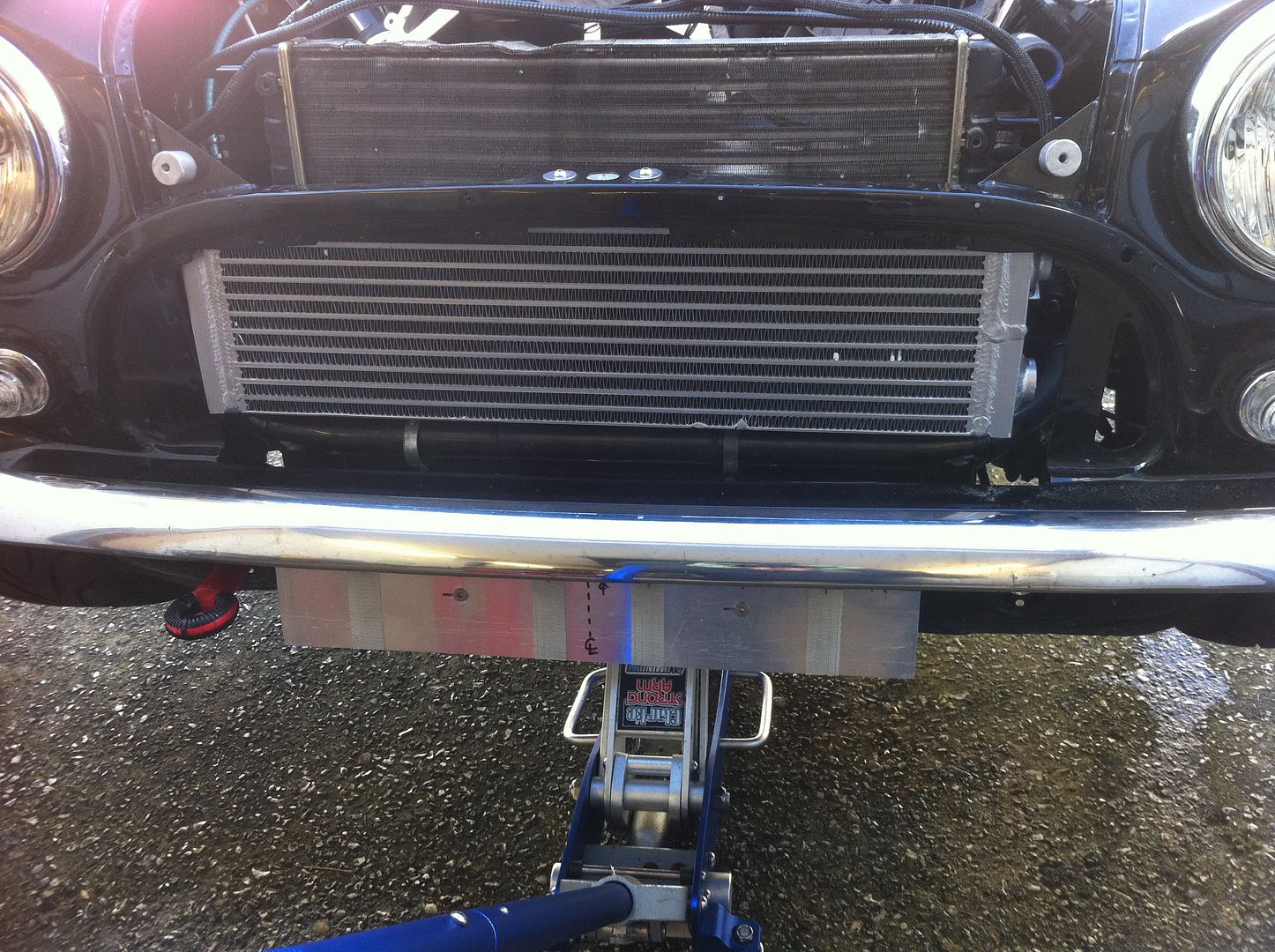
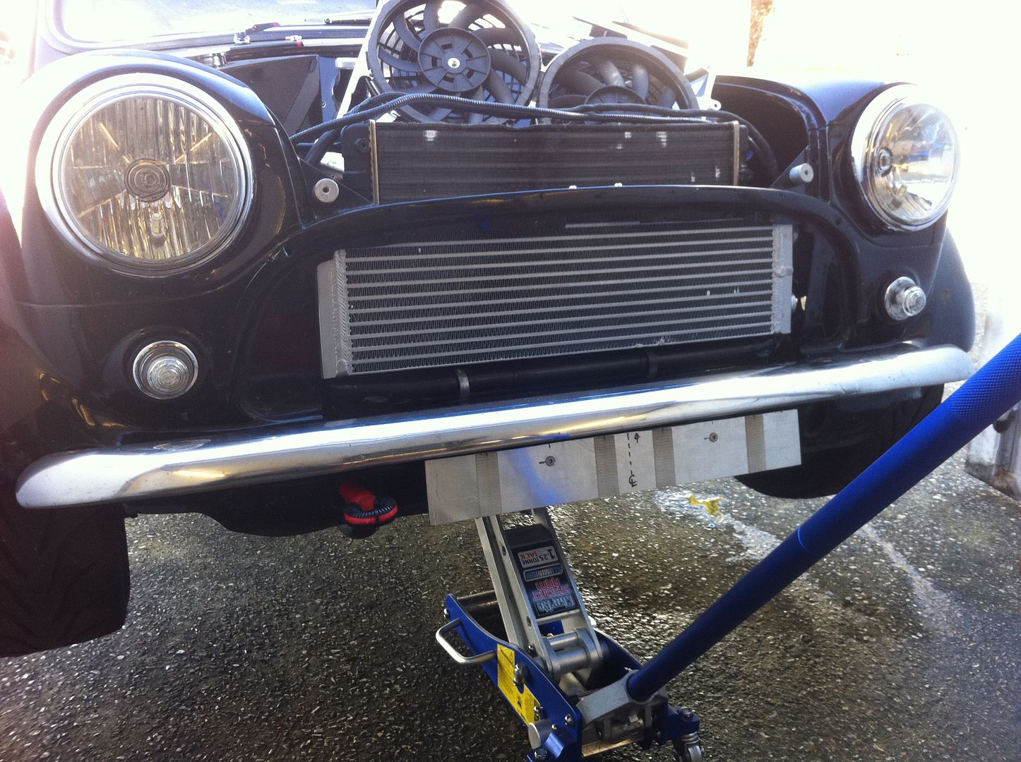
I spent the morning trying fit my pre-rad in, safe to say it wasnt straight forward. The front engine radiator mount had to be removed and the lump of pastic that was the fixing hole on the engine radiator. The tabs that were on the top and bottom of the pre-rad needed to be removed, then it was a quick snap fo the engine rad as is then I began work and it'll never look the same again.
So a run of photos showing the rad how it is now then onto offering it up, chopping the mount and finally the pre-rad in situ......
#775

Posted 19 February 2012 - 02:52 PM
#776

Posted 19 February 2012 - 04:49 PM
#777

Posted 19 February 2012 - 05:34 PM
#778

Posted 26 February 2012 - 01:43 AM
#779

Posted 27 February 2012 - 12:51 PM
My god i have not been on here for ages and ages so i thought id have a quick gander and you have got the beast in bits again lol...... whats going on man !!..... i see your putting a charge cooler in always a good idea in my book, the more cooling the better, what are you hoping to achieve, do you think it will make much of a difference its a pretty sweet setup as it is, has anyone done anything like this before or is this a captain kirk moment of genius i must admit it does look like a really effect bit of cooling i hope it works, did you see my twin rad setup for the charge cooler in the front they bolt together and fit really neat.
Hey Claudio, long time.
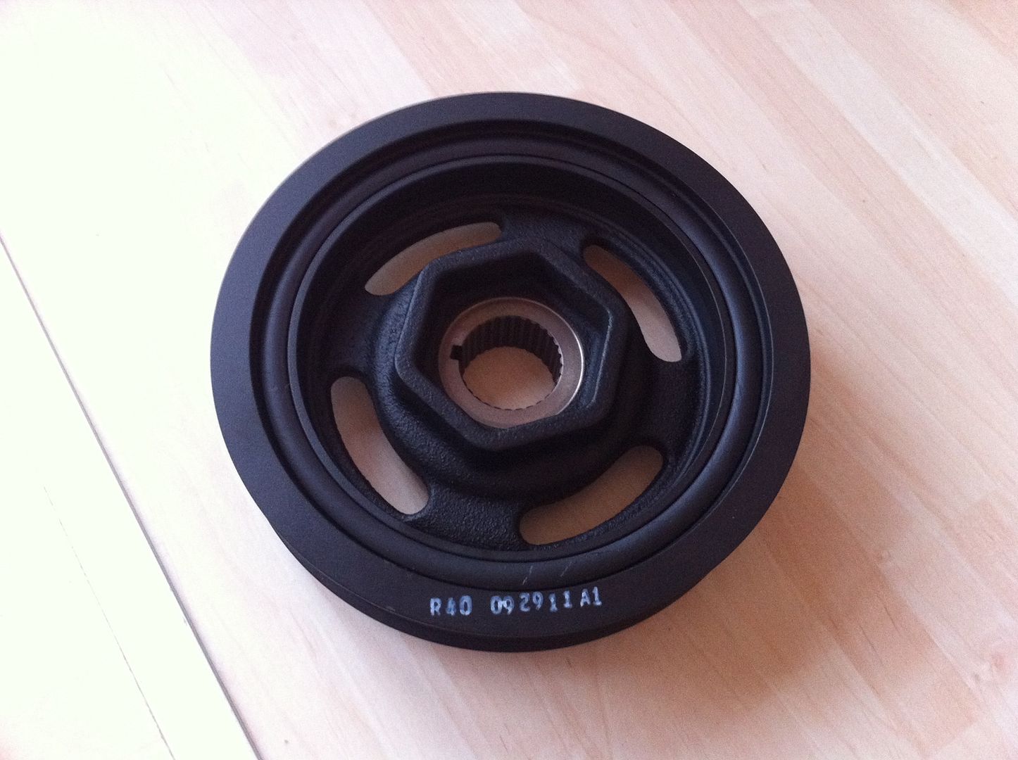
I am not only charge cooling it but I am putting on a bigger crank pulley (6.37" - original is 5.465") (this will help with low rev water flow) and believe it or not a bigger blower pulley (3.4" from a 3.3"), now that might sound odd as you would normally put on a smaller blower pulley to spin the blower faster. In this case the CP is that much bigger that it would be spinning the blower beyond its comfort zone. With the new setup the blower is spinning approx 2000rpm faster than before (was 14500rpm, now 16500rpm @ 8800 engine rpm). The actuall PSI seen in the manifold wont be that much greater as there will be a pressure drop in the intercooler, not as great as an air to air I/C but still an amount.
I also never got around to finishing my new manifold to go between the throttle body and charger, this will be done and I will be fitting the 72mm throttle body to it along with a new air filter I should see some serious gains. It was 288HP at the hubs last time on the dyno - I am going to wet finger in the air and say I am hoping for 340-350hp at the hubs, if it does come in at that I will be very happy. To get a BHP figure at the crank I add 10% for drivetrain losses.
I cant admit to it being all my idea as others have put an intercooler in the same position but none with the same cooler as mine as it is a bespoke item.
I never did see the twin rad setup, maybe post it up in your build diary for us to see, so others might have an idea of how to do it.
#780

Posted 08 March 2012 - 12:50 PM
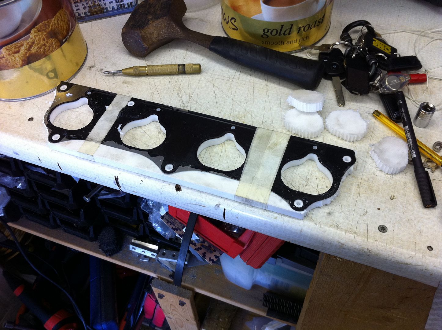
I am going to stick with the Acetal between the charger/aftercooler and the aftercooler/manifold.
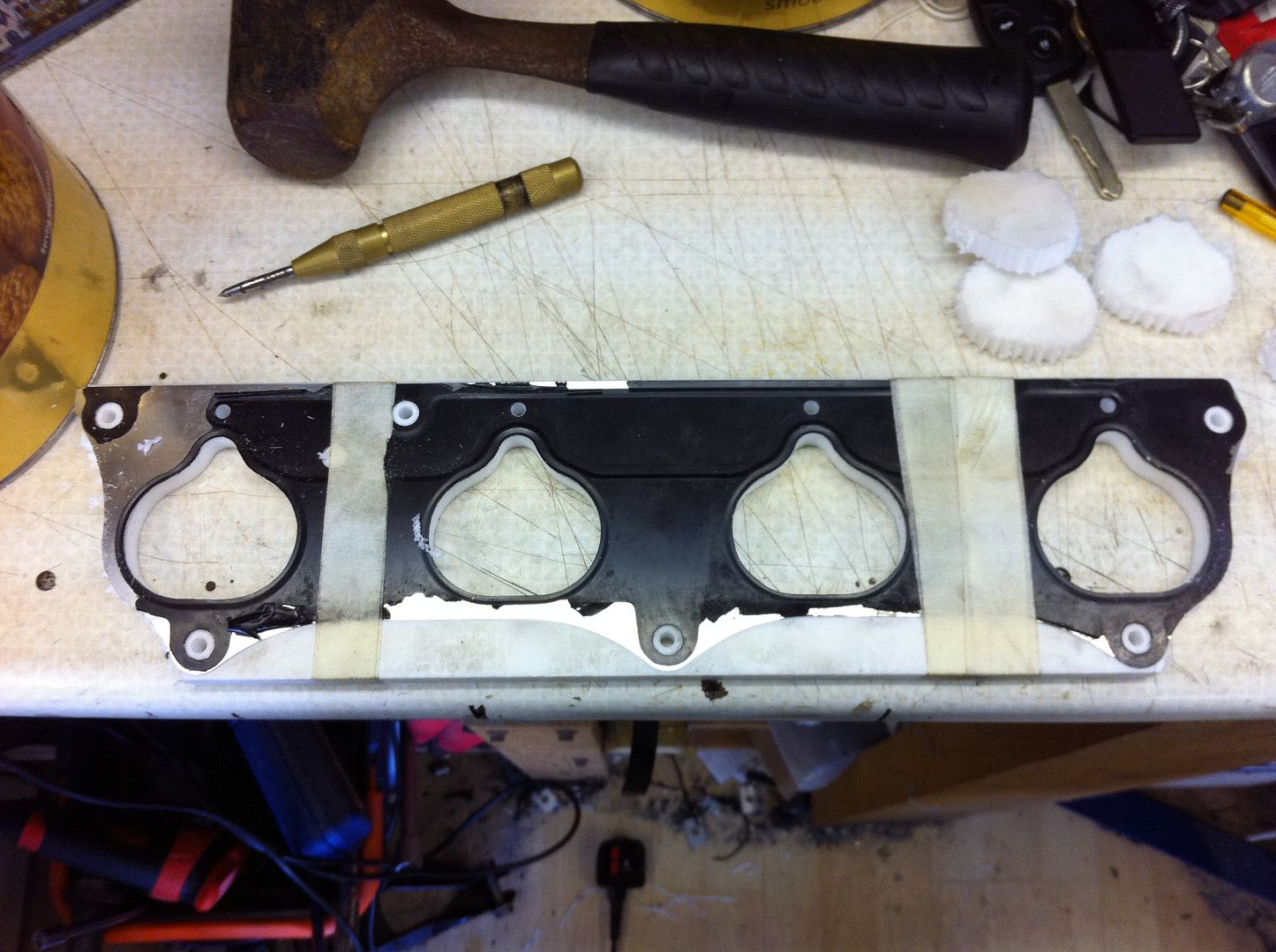
The PTFE is also much easier to work with if you have limited resources, again I produced the part with a pillar drill, a 4mm drill for chain drilling, a 12mm drill for the top of the ports and then also for smoothing the ports and finally a 9mm drill for the bolt holes. Be warned if using a hand drill the material will pull you into it as it is quite soft material.
Unfortunately the only photo I took so far is with the OEM gasket on it being used as a template.
And this came through the post the other day (K24 crank pulley, 6.37"):
I need to start extracting the digit or summer will be here before I know it.
.
1 user(s) are reading this topic
0 members, 1 guests, 0 anonymous users


