Supercharged K20a2 Vtec - Race Spec
#151
Posted 28 May 2009 - 08:55 PM
Secondly I have been concentrating on the wiring loom(s), I have to say that I dont have much experience in wiring cars and this is really testing me. It's made even more difficult when there is no wiring diagram for the main loom. It may be time to admit defeat - I will wait until after the weekend and see if I can get my head around it. Need to order a few switches anyway.
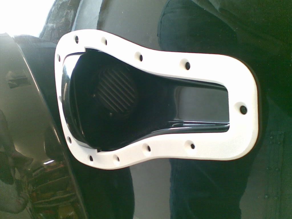
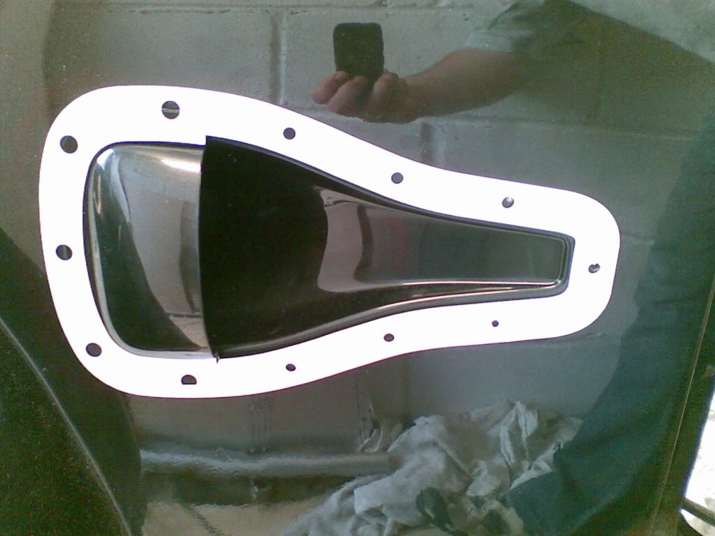
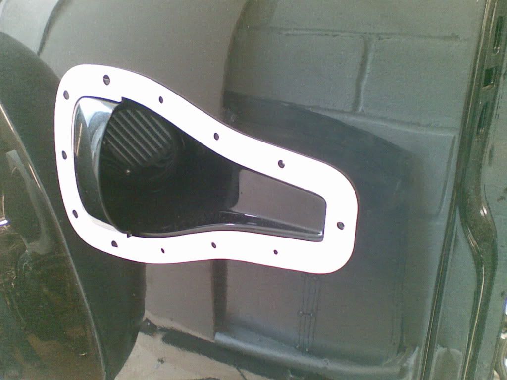
Back to the scoop plates.....
So here are a few snaps of a plate offered up - literally offered up, not sitting flush yet as not bolted down......
#152
Posted 28 May 2009 - 09:56 PM
Rob
#153
Posted 29 May 2009 - 08:45 AM
yes I am using the Z's wiring loom, I have every wire labeled up but still somethings are just baffling me.
One thing I cannot for the life of me find is where to connect the reverse light switch to.....????
If you have a diagram that would be a massive help and greatly appreciated.
Cheers
Andy
#154
Posted 29 May 2009 - 12:01 PM
#155
Posted 29 May 2009 - 03:34 PM
#156
Posted 29 May 2009 - 07:49 PM
One thing I cannot for the life of me find is where to connect the reverse light switch to.....????
OK, so I have sussed out where to connect the reverse light to. There are two wires that are marked up as to be used for the reverse switch - pretty bloody obvious really. When I first looked I thought it was for the reversing motor switch for the bike engined cars - we live and learn.
So the wiring loom is starting to make more sense the more testing I do, you have to just make things live and start working it all out, it's definitely not a 5min job, thats for sure. I have all this weekend to get my head around it, lets hope there's enough time to get it done for August.
Need to make a battery holder tomorrow, should have some pictures of that by the end of the weekend.
#157
Posted 29 May 2009 - 07:52 PM
Hey mate, i really admire your sheer comitment and time you'v burried into this project. i live the engine your using and the "rear bulkhead" it kinda makes everything look more presentable.. and as for the bodywork you've done.. WOW mate. GOOD JOB!!!
Thanks, I cant wait for it all to come together, should be different to anything else, still a few surprises in store.
#158
Posted 31 May 2009 - 04:33 PM
Didnt get time to make a battery holder so that'll have to wait til one night in the week.
#159
Posted 02 June 2009 - 09:28 PM
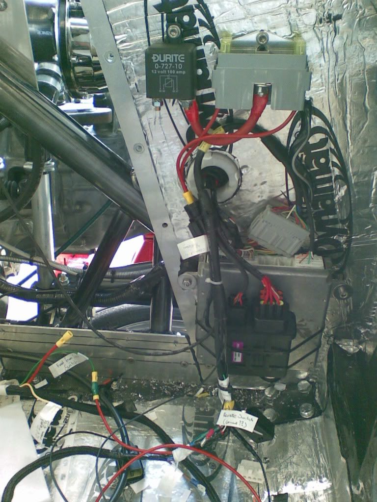
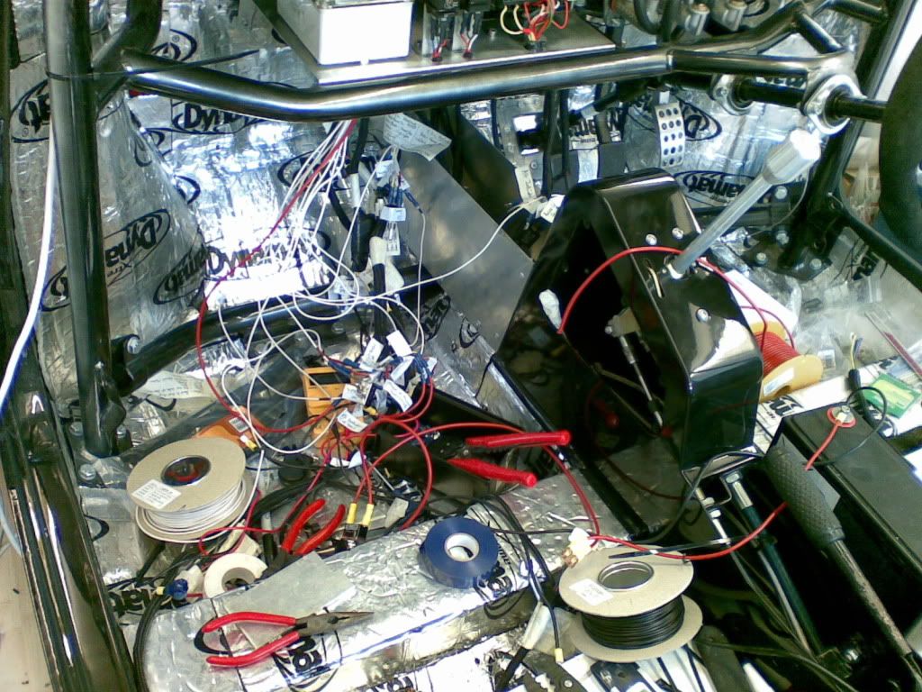
Made a bit more progress tonight after realising that I didnt have a main beam flash circuit in my setup I now have another relay in palce for that. Just a couple of photos to show the snakes wedding in progress, note the 'in progress'.......
I have to admit that although I was not experienced in auto electrics I do however have an understanding of electrics and electronics (got a GCSE in electronics) so I had the basics but was put off by the unknown. It isnt easy and is you dont have any experience of electrics or electronics then I would leave it up to the pro's.
Not for the faint hearted - thats for sure.....
#160
Posted 02 June 2009 - 09:32 PM
Sorry I am not at work this week so I cant seem to send you this drawing. will try again though.
Rob
#161
Posted 03 June 2009 - 07:22 AM
Yer no worries, making good progress now so the drawing may be more of a checking process.
Andy
#162
Posted 03 June 2009 - 05:28 PM
Good luck on it all keep us updated!
Very very tidy though. impressed with it all
#163
Posted 05 June 2009 - 04:21 PM
just one thing when all the wiring is done you need to cut all the bullet connectors off and solder all the wires or proper plugs, as they get corroded and will cause you problems in the future.
#164
Posted 06 June 2009 - 12:35 AM
What exactly is the "multi function relay unit"? Is that a Honda part or something you can use in place of several relays to switch different loads? i.e. one power into the unit, but several switched powers out controlled by several inputs...
#165
Posted 06 June 2009 - 02:37 AM
1 user(s) are reading this topic
0 members, 1 guests, 0 anonymous users